1. Inputs
ARMI input files define the initial state of the reactor model and tell ARMI what kind of analysis should be performed on it.
Note
We have a Building input files for a fast reactor tutorial for a quick overview of the inputs.
There are several input files:
- Settings file
Contains simulation parameters (like full power, cycle length, and which physics modules to activate) and all kinds of modeling approximation settings (e.g. convergence criteria)
- Blueprints file
Contains dimensions and compositions of the components/blocks/assemblies in your reactor systems, from fuel pins to heat exchangers
- Fuel management file
Describes how fuel moves around during a simulation
Depending on the type of analysis, developers may create other input files for things like: control logic, ex-core models for transients and shielding, etc.
1.1. YAML Files
ARMI’s input files all use the YAML format. This is a well-known file format, chosen because it is human-readable and easy to hand-write. That being said, there are two details about the YAML format that are important to know:
- Ordering
YAML is not order specific; however, one of the techniques used to limit the size of the input includes using YAML anchors to reuse block and component definitions. YAML anchors (e.g.
&block_name) must be defined before their corresponding alias (e.g.*block_name) used.- Duplicate Keys
YAML allows for duplicate keys. However, in ARMI, duplicates might be erroneous. Unfortunately, because the international YAML specification allows for duplicates, none of the YAML-parsing libraries see it as an error. You will have to hand-verify your inputs are correct.
1.2. The Settings Input File
The settings input file defines a series of key/value pairs the define various information about the system you are modeling as well as which modules to run and various modeling/approximation settings. For example, it includes:
The case title
The reactor power
The number of cycles to run
Which physics solvers to activate
Whether or not to perform a critical control search
Whether or not to do tight coupling iterations
What neutronics approximations specific to the chosen physics solver to apply
Environment settings (paths to external codes)
How many CPUs to use on a computer cluster
This file is a YAML file that you can edit manually with a text editor or with the ARMI GUI.
Here is an excerpt from a settings file:
settings:
# global
  availabilityFactor: 1
  beta: 0.003454
  branchVerbosity: debug
  buGroups:
    - 100
  burnSteps: 2
  comment: Simple test input.
  cycleLength: 2000.0
  detailAssemLocationsBOL:
    - 002-001
  freshFeedType: igniter fuel
  loadingFile: refSmallReactor.yaml
A full listing of settings available in the framework may be found in the Table of all global settings .
Many settings are provided by the ARMI Framework, and others are defined by various plugins.
1.2.1. The ARMI GUI
The ARMI GUI may be used to manipulate many common settings (though the GUI can’t change all of the settings). The GUI also enables the graphical manipulation of a reactor core map, and convenient automation of commands required to submit to a cluster. The GUI is a front-end to these files. You can choose to use the GUI or not, ARMI doesn’t know or care – it just reads these files and runs them.
Note that one settings input file is required for each ARMI case, though many ARMI cases can refer to the same Blueprints, Core Map, and Fuel Management inputs.
Note
The ARMI GUI is not yet included in the open-source ARMI framework, but a simple grid editor GUI is, as described in Grids
1.2.1.1. The assembly clicker
The assembly clicker (aka the Grid Editor) allows users to define the 2-D layout of the assemblies defined in the The Blueprints Input File. This can be done in hexagon or cartesian. The results of this arrangement get written to grids in blueprints. Click on the assembly palette on the right and click on the locations where you want to put the assembly. By default, the input assumes a 1/3 core model, but you can create a full core model through the menu.
If you want one assembly type to fill all positions in a ring, right click it once it is placed and choose Make ring like this hex. Once you submit the job or save the settings file (File -> Save), you will be prompted for a new name of the geometry file before the settings file is saved. The geometry setting in the main tab will also be updated.
1.2.1.2. The ARMI Environment Tab
The environment tab contains important settings about which version of ARMI you will run and with which version of Python, etc. Most important is the ARMI location setting. This points to the codebase that will run. If you want to run the released version of ARMI, ensure that it is set in this setting. If you want to run a developer version, then be sure to update this setting.
Other settings on this tab may need to be updated depending on your computational environment. Talk to your system admins to determine which settings are best.
1.2.2. Some special settings
A few settings warrant additional discussion.
1.2.2.1. Detail assemblies
Many plugins perform more detailed analysis on certain regions of the reactor. Since the analyses often take longer, ARMI has a feature, called detail assemblies to help. Different plugins may treat detail assemblies differently, so it’s important to read the plugin documentation as well. For example, a depletion plugin may perform pin-level depletion and rotation analysis only on the detail assemblies. Or perhaps CFD thermal/hydraulics will be run on detail assemblies, while subchannel T/H is run on the others.
Detail assemblies are specified by the user in a variety of ways, through the GUI or the settings system.
Warning
The Detail Assemblies mechanism has begun to be too broad of a brush for serious multiphysics calculations with each plugin treating them differently. It is likely that this feature will be extended to be more flexible and less surprising in the future.
- Detail Assembly Locations BOL
The
detailAssemLocationsBOLsetting is a list of assembly location strings (e.g.004-003for ring 4, position 3). Assemblies that are in these locations at the beginning-of-life will be activated as detail assemblies.- Detail assembly numbers
The
detailAssemNumssetting is a list ofassemNums that can be inferred from a previous case and specified, regardless of when the assemblies enter the core. This is useful for activating detailed treatment of assemblies that enter the core at a later cycle.- Detail all assemblies
The
detailAllAssemssetting makes all assemblies in the problem detail assemblies
1.2.2.2. Kinetics settings
In reactor physics analyses it is standard practice to represent reactivity in either absolute units (i.e., dk/kk’ or pcm) or in dollars or cents. To support this functionality, the framework supplies the beta and decayConstants settings to apply the delayed neutron fraction and precursor decay constants to the Core parameters during initialization.
These settings come with a few caveats:
The
betasetting supports two different meanings depending on the type that is provided. If a single value is given, then this setting is interpreted as the effective delayed neutron fraction for the system. If a list of values is provided, then this setting is interpreted as the group-wise (precursor family) delayed neutron fractions (useful for reactor kinetics simulations).The
decayConstantssetting is used to define the precursor decay constants for each group. When set, it must be provided with a correspondingbetasetting that has the same number of groups. For example, if six-group delayed neutron fractions are provided, the decay constants must also be provided in the same six-group structure.If
betais interpreted as the effective delayed neutron fraction for the system, then thedecayConstantssetting will not be utilized.If both the group-wise
betaanddecayConstantsare provided and their number of groups are consistent, then the effective delayed neutron fraction for the system is calculated as the summation of the group-wise delayed neutron fractions.
1.2.2.3. Cycle history
For all cases, nCycles and power must be specified by the user. In the case that only a single state is to be examined (i.e. no burnup), the user need only additionally specify nCycles = 1.
In the case of burnup, the reactor cycle history may be specified using either the simple or detailed option. The simple cycle history consists of the following case settings:
power
nCycles(default = 1)
burnSteps(default = 4)
availabilityFactor(s)(default = 1.0)
cycleLength(s)(default = 365.2425)
In addition, one may optionally use the powerFractions setting to change the reactor power between each cycle. With these settings, a user can define a history in which each cycle may vary in power, length, and uptime.
The “uptime” being the amount of time the reactor is at power * powerFractions[i] for cycle i.
The uptime duration is determined by cycleLengths[i] * availabilityFactors[i] days with “downtime” cycleLengths[i] * (1 - availabilityFactors[i]).
The cycle length is then the amount of total time (uptime + downtime) between the start of two successive cycles.
The history is restricted, however, to each cycle having a constant power, to each cycle having the same number of burnup nodes, and to those burnup nodes being evenly spaced within each cycle. An example simple cycle history might look like
settings:
    power: 1000000
    nCycles: 3
    burnSteps: 2
    cycleLengths: [100, R2]
    powerFractions: [1.0, 0.5, 1.0]
    availabilityFactors: [0.9, 0.3, 0.93]
Note the use of the special shorthand list notation, where repeated values in a list can be specified using an “R” followed by the number of times the value is to be repeated.
The above scheme would represent 3 cycles of operation:
100% power for 90 days, split into two segments of 45 days each, followed by 10 days shutdown (i.e. 90% capacity)
50% power for 30 days, split into two segments of 15 days each, followed by 70 days shutdown (i.e. 15% capacity)
100% power for 93 days, split into two segments of 46.5 days each, followed by 7 days shutdown (i.e. 93% capacity)
In each cycle, criticality calculations will be performed at 3 (burnSteps + 1) nodes evenly-spaced through the uptime portion of the cycle, without option for changing node spacing or frequency.
A more detailed cycle history may be specified using the cycles setting. For each cycle, an entry to the cycles list is made with the following optional fields:
name
power fractions
cumulative days,step days, orburn steps+cycle length
availability factor
An example detailed cycle history employing all of these fields could look like
settings:
    power: 1000000
    nCycles: 4
    cycles:
      - name: A
        step days: [1, 1, 98]
        power fractions: [0.1, 0.2, 1]
        availability factor: 0.1
      - name: B
        cumulative days: [2, 72, 78, 86]
        power fractions: [0.2, 1.0, 0.95, 0.93]
      - name: C
        step days: [5, R5]
        power fractions: [1, R5]
      - cycle length: 100
        burn steps: 2
        availability factor: 0.9
Note that repeated values in a list may be again be entered using the shorthand notation for step days, power fractions, and availability factors (though not cumulative days because entries must be monotonically increasing).
Such a scheme would define the following cycles:
A 2 day power ramp followed by full power operations for 98 days, with three nodes clustered during the ramp and another at the end of the cycle, followed by 900 days of shutdown,
A 2 day power ramp followed by a prolonged period at full power and then a slight power reduction for the last 14 days in the cycle,
Constant full-power operation for 30 days split into six even increments,
Constant full-power operation for 90 days, split into two equal-length 45 day segments, followed by 10 days of downtime,
As can be seen, the detailed cycle history option provides much flexibility for simulating realistic operations, particularly power ramps or scenarios that call for unevenly spaced burnup nodes, such as xenon buildup in the early period of thermal reactor operations.
Note
Although the detailed cycle history option allows for powers to change within each cycle, it should be noted that the power over each step is still considered to be constant.
Note
The name field of the detailed cycle history is not yet used for anything, but this information will still be accessible on the operator during runtime.
Note
Cycles without names will be given the name None
Warning
When a detailed cycle history is combined with tight coupling, a subclass of LatticePhysicsInterface.interactCoupled should be used.
1.2.2.4. Restart cases
Oftentimes the user is interested in re-examining just a specific set of time nodes from an existing run. In these cases, it is sometimes not necessary to rerun an entire reactor history, and one may instead use one of the following options:
Snapshot, where the reactor state is loaded from a database and just a single time node is run.
Restart, where the cycle history is loaded from a database and the calculation continues through the remaining specified time history.
For either of these options, it is possible to alter the specific settings applied to the run by simply adjusting the case settings for the run. For instance, a run that originally had only neutronics may incorporate thermal hydraulics during a snapshot run by adding in the relevant TH settings.
Note
For either of these options, it is advisable to first create a new case settings file with a name different than the one from which you will be restarting off of, so as to not overwrite those results.
To run a snapshot, the following settings must be added to your case settings:
Set
runTypetoSnapshotsAdd a list of cycle/node pairs corresponding to the desired snapshots to
dumpSnapshotformatted as'CCCNNN'Set
reloadDBNameto the existing database file that you would like to load the reactor state from
An example of a snapshot run input:
runType: Snapshots
reloadDBName: my-old-results.h5
dumpSnapshot: ['000000', '001002'] # 2 snapshots at BOL and cycle 1-node 2
To run a restart, the following settings must be added to your case settings:
Set
runTypetoStandardSet
loadStyletofromDBSet
startCycleandstartNodeto the cycle/node that you would like to continue the calculation from (inclusive).startNodemay use negative indexing.Set
reloadDBNameto the existing database file from which you would like to load the reactor history up to the restart pointIf you would like to change the specified reactor history (see Restart cases), keep the history up to the restarting cycle/node unchanged, and just alter the history after that point. This means that the cycle history specified in your restart run should include all cycles/nodes up to the end of the simulation. For complicated restarts, it may be necessary to use the detailed
cyclessetting, even if the original case only used the simple history option.
A few examples of restart cases:
- Restarting a calculation at a specific cycle/node and continuing for the remainder of the originally-specified cycle history:
- Add an additional cycle to the end of a case:
- Restart but cut the reactor history short:
- Restart with a different number of steps in the third cycle using the detailed
cyclessetting:
Note
The skipCycles setting is related to skipping the lattice physics calculation specifically, it is not required to do a restart run.
Note
The ISO binary cross section libraries are required to run cases that skip the lattice physics calculation (e.g. MC^2)
Note
Restarting a calculation with an different version of ARMI than what was used to produce the restarting database may result in undefined behavior.
1.2.2.5. Shuffling
Note
The explicitRepeatShuffles setting points to a *-SHUFFLES.txt file that records moves from a previous
run for exact repetition.
Users may also define a custom shuffle plan in a YAML file referenced by the shuffleSequenceFile setting. The YAML
format organizes data by cycle in a sequence mapping. Keys are the cycle where the shuffling should occur during
the beginning-of-cycle step. The first available cycle where shuffling will occur is cycle 1. Each cycle contains a
list of high-level actions. An action is a mapping containing one of the keys cascade, swap, or
extraRotations. cascade chains describe a sequence of assembly displacements beginning with a fresh fuel
assembly and ending with the final location’s assembly being discharged. Optional fuelEnrichment lists specify the
U235 weight fraction enrichment for each axial block in the fresh assembly, from bottom to top, including zeroes for
non-fuel blocks. swap swaps the assemblies at two locations after all cascades are processed.
extraRotations map final location labels to relative counterclockwise angles in degrees and are applied after all
cascades, swaps, and any algorithmic rotation routines defined with the assemblyRotationAlgorithm setting.
The angle is relative to the assembly’s current orientation and whatever assembly ends up at the given location is
rotated. Valid angles depend on the assembly’s geometry.
Extra rotations therefore:
apply to whatever assembly resides at the specified location once all cascades and swaps are complete;
rotate the assembly relative to its current orientation; and
execute after any algorithmic rotation routines.
A cascade with no final destination defaults to deleting the assembly. Assemblies can be retained in the model by
ending the cascade with SFP. When SFP is specified, the discharged assembly is stored in the spent fuel pool
even if the trackAssems setting is False; Delete always removes the assembly from the model.
Assemblies may also be re-inserted from the spent fuel pool by starting a cascade with SFP and providing a
ringPosCycle to identify the spent fuel pool assembly returning to the core. ringPosCycle is a list conatining
ring, pos, and cycle used to specify that the assembly which resided at (ring, pos) during the specified cycle number
is to be re-introduced into the reactor in the associated shuffle cascade. No assembly type is required in this case.
The cascade then proceeds as normal from the destination location. For example
sequence:
  1:
    - cascade: ["outer fuel", "009-045", "008-004", "SFP"]
      fuelEnrichment: [0, 0.12, 0.14, 0.15, 0]  # wt fraction U235 by block
    - swap: ["009-045", "008-004"]
    - extraRotations: {"009-045": 60}
  2:
    - cascade: ["outer fuel", "010-046", "009-045", "Delete"]
      fuelEnrichment: [0, 0.12, 0.14, 0.15, 0]
A cascade that loads an assembly from the SFP may look like:
.. code:: yaml
- sequence:
- 1:
cascade: [“SFP”, “005-003”, “SFP”] ringPosCycle: [3, 5, 4]
This example retrieves the assembly that resided at ring 3, position 5 during cycle 4 from the spent fuel pool and
places it in location 005-003 (ring 5, position 3) while sending the previous occupant of 005-003 to the spent
fuel pool.
Note
Consider using yaml anchors & and aliases * to reduce repetition.
For cycle 1 above, the actions execute in the following order:
The assembly originally at
008-004is discharged to the spent fuel poolSFP.The assembly originally at
009-045moves to008-004.A fresh
outer fuelassembly is created with the specified axial enrichment profile and inserted at009-045.The fresh assembly and the moved assembly at
008-004are swapped, leaving the fresh assembly at008-004and the moved assembly back at009-045.The assembly now at
009-045is rotated an additional 60 degrees counterclockwise.
Note
The restart.dat file is required to repeat the exact fuel management methods during a branch search. These can potentially modify the reactor state in ways that cannot be captures with the SHUFFLES.txt file.
1.2.2.6. Zones
Zones are a collection of assemblies that share some similar characteristics. A zone might be those assemblies with
a similar orrificing pattern or a some subset of fuel assemblies. Some codes may wish to study behavior by lumping the
reactor into a few channels with bulk or aggregated properties. Users can collect assemblies in each of these channels
through the zones attribute on the core. See also the
Zones class.
Users can define these zones with the zonesFile setting. It must point to YAML file that contains the high-level key
customZonesMap containing a map of location: zone maps.
customZonesMap:
  001-001: primary control
  002-001: fuel z0
  003-001: fuel z0
  004-001: fuel z1
  004-002: secondary control
The location keys are the ARMI ring-position assembly identifier. It is not required to have every assembly be
inside a zone. But assemblies not listed will not be added to any zone, i.e., there is no default zone.
This example would produce four zones:
primary controlcontaining the center assembly at001-001,fuel z0containing two fuel assemblies:002-001and003-001,fuel z1containing one fuel assembly:004-001, andsecondary controlcontaining the assembly at004-002.
An alternative method is with the zoneDefinitions setting in the primary settings file. This contains a list of
zone names and the assemblies that make up that zone. The following would create an identical zone structure as above.
settings:
  zoneDefinitions:
    - "primary control: 001-001"
    - "fuel z0: 002-001, 003-001"
    - "fuel z1: 004-001"
    - "secondary control: 004-002"
Note
These are list of strings, not additional maps. Wrapping in quotations is required to process the zone definitions.
These zones will be populated according to the buildManualZones() core method.
1.3. The Blueprints Input File
The blueprints input defines the dimensions of structures in the reactor, as well as their material makeup. In a typical case, pin dimensions, isotopic composition, control definitions, coolant type, etc. are defined here. The specifics of each assembly type are then overlaid, possibly including enrichment distributions and other material modifications.
Note
See the blueprints module for implementation and more detail.
This input file is formatted using YAML, which allows text-based change tracking for design control. ARMI does not have a blueprints-editing GUI yet, but may in the future.
Note
You can point many ARMI runs to the same Blueprints input file using full paths in loadingFile setting.
ARMI adds an !include YAML tag, which can be used to include the contents of an external YAML file in any part of a blueprints file. The can be useful for sharing core or assembly pin layouts amongst multiple cases. For example:
grids:
    core: !include path/to/core_grid.yaml
would have the effect of copy-pasting the contents of path/to/core_grid.yaml into the main blueprints file. The rules that ARMI uses to handle things like indentation of the included text are usually rather intuitive, but sometimes it can be useful to witness the behavior first-hand. The expand-bp command can be used to do a dry run for testing inputs with !includes.
ARMI models are built hierarchically, first by defining components, and then by larger and larger collections of the levels of the reactor.
1.3.1. Blueprint sections
The blueprints input file has several sections that corresponds to different levels of the reactor hierarchy. You will generally build inputs “bottoms up”, first by defining elementary pieces (like pins) and then collecting them into the core and reactor.
The ARMI data model is represented schematically below, and the blueprints are defined accordingly:
The primary data containers in ARMI
- blocks:
Defines
Componentinputs for aBlock.- assemblies:
Defines vertical stacks of blocks used to define the axial profile of an
Assembly.- systems:
Reactor-level structures like the core, the spent fuel pool, pumps, the head, etc.
- grids:
Lattice definitions for the core map or pin maps
- nuclide flags:
Special setting: Specifies nuclide modeling options, whether a nuclide is being modeled for cross sections and/or depletion. For instance, it allows you to ignore nuclides above Curium for depletion speed. This also allows you to expand elements to a subset of nuclides. For example, you can choose to expand Oxygen to just Oxygen-16 and neglect Oxygen-17 and 18.
- custom isotopics:
Special setting: defines user-specified isotopic compositions.
The core map input files can be graphically manipulated with the
Grid editor.
1.3.2. Blocks and Components
Blocks and components are defined together in the blueprints input.
We will start with a component, and then define the whole blocks: input. The structure will be something like:
blocks:
    block name 1:
        component name 1:
            ...
        component name 2:
    block name 2:
        component name 1:
            ...
        component name 2:
            ...
Note
You can also define components at the top level of the blueprints file under the components: top level
section, but bringing anything defined there into the reactor model must currently be done programmatically. We are
currently developing additional input capabilities to use these more flexibly.
Associated with this is a component groups: section which can collect different free components with different
volume fractions. This also is not fully implemented yet.
1.3.2.1. Defining a Component
The Components section defines the pin (if modeling a pin-type reactor) and assembly in-plane dimensions (axial
dimensions are defined in the Assemblies input) and the material makeups of each
Component. Blocks are defined here as collections
of geometric components that have specific temperatures, dimensions, material properties, and isotopic compositions.
An component may be defined as:
fuel:
    shape: Circle
    material: UZr
    Tinput: 20.0
    Thot: 450.0
    mult: 169
    id: 0.0
    od: 0.757
Here we have provided the following information:
- Component name
The component name (
fuel) is specified at the top. Some physics kernels interpret names specially, so pay attention to any naming conventions. As a general rule, you can expect that people will be doing regex on your name, so you should not use any of these characters in your component names:. ^ $ * + ? { } [ ] \ | ( ) :.- shape
The shape will be extruded to the length specified in the
assembliesinput section below. ARMI contains a variety of built-in simple shapes, and plugins can define their own design-specific/proprietary shapes.- material
The material links the component to a certain set of thermo-physical properties (e.g. temperature-dependent thermal expansion coefficients, density, thermal conductivity, etc., which are used in the various physics kernels. Natural isotopic composition is determined from this material specification as well (unless custom isotopics are supplied). The entry here should either be a class name of a valid material (
UZr) or amodule:classNamepair for specifying specific material (e.g.armi.materials.uZr:UZr). Materials are handled through thematerial library.- Tinput
The temperature (in C) that corresponds to the input dimensions given here. This facilitates automatic thermal expansion.
- Thot
The temperature (in C) that the component dimensions will be thermal expanded to (using material properties based on the
materialinput). To disable automatic thermal expansion, set Tinput and Thot both to the same value- mult
Multiplicity specifies how many duplicates of this component exist in this block. If you want 169 pins per assembly, this would be 169. This does not explicitly describe the location of the pins. Note that many fast-neutron systems only need volume fractions, not precise spatial locations, at least for pre-conceptual/simple studies.
- id
Inner diameter (in cm). Each shape has different required input dimension keys. For annulus, set id to non-zero.
- od
Outer diameter (in cm).
1.3.2.2. Component Types
Each component has a variety of dimensions to define the shape and composition. All dimensions are in cm. The following is a list of included component shapes and their dimension inputs. Again, additional/custom components with arbitrary dimensions may be provided by the user via plugins.
Component Name |
Dimensions |
|---|---|
Component |
|
ShapedComponent |
|
Circle |
od, id, mult, modArea |
Hexagon |
op, ip, mult, modArea |
Rectangle |
lengthOuter, lengthInner, widthOuter, widthInner, mult, modArea |
SolidRectangle |
lengthOuter, widthOuter, mult, modArea |
Square |
widthOuter, widthInner, mult, modArea |
Triangle |
base, height, mult, modArea |
HoledHexagon |
op, holeOD, nHoles, holeRadFromCenter, mult, modArea |
CircleHoledCircle |
od, holeOD, nHoles, holeRadFromCenter, mult, modArea |
HexHoledCircle |
od, holeOP, mult, modArea |
FilletedHexagon |
op, ip, iR, oR, mult, modArea |
HoledRectangle |
holeOD, lengthOuter, widthOuter, mult, modArea |
HoledSquare |
holeOD, widthOuter, mult, modArea |
Helix |
od, axialPitch, helixDiameter, mult, id, modArea |
Sphere |
od, id, mult, modArea |
Cube |
lengthOuter, lengthInner, widthOuter, widthInner, heightOuter, heightInner, mult, modArea |
RadialSegment |
inner_radius, outer_radius, height, mult, inner_theta, outer_theta |
DifferentialRadialSegment |
inner_radius, radius_differential, inner_axial, height, inner_theta, azimuthal_differential, mult |
NullComponent |
|
UnshapedComponent |
modArea |
UnshapedVolumetricComponent |
op, volume |
ZeroMassComponent |
op, volume |
PositiveOrNegativeVolumeComponent |
op, volume |
DerivedShape |
modArea |
When a DerivedShape is specified as the final component in a block, its area is inferred from the difference
between the area of the block and the sum of the areas comprised by the other components in the block. This is useful
for complex shapes like coolant surrounding a lattice of pins.
1.3.2.3. Component Links
Dimensions of a component may depend on the dimensions of a previously-defined component in the same block. For
instance, the sodium bond between fuel and cladding. The format is simply <componentName>.<dimensionName>. The
dimension names are available in the table above.
blocks:
    fuel:                       # block name
        fuel:                   # component name
            shape: Circle
            material: UZr
            Tinput: 25.0
            Thot: 600.0
            id: 0.0
            isotopics: LABEL1
            mult: 169.0
            od: 0.757
        bond:
            shape: Circle
            material: Sodium
            Tinput: 450.0
            Thot: 450.0
            mult: fuel.mult
            id: fuel.od         # bond is connected to the outside of fuel
            od: clad.id         # and the inside of the clad
        clad:
            shape: Circle
            material: HT9
            Tinput: 25.0
            Thot: 450.0
            id: 0.905
            mult: fuel.mult
            od: 1.045
Linked component dimensions (such as bond.id being linked to fuel.od) remain linked as dimensions change. For
example when the above defined fuel is expanded from cold temperature of 25 to the hot temperature of 600 the
bond.id will still be whatever the fuel.od is. This can result in the displacement of material. For example, in
the above case, if the fuel expansion removes more cross sectional area than the clad expansion creates, the amount of
thermal bond will be reduced. This is physical since, in reality, the fluid would be displaced as dimensions change.
1.3.2.4. Pin lattices
Pin lattices may be explicitly defined in the block/component input in conjunction with the grids input section. A
block may assigned a grid name, and then each component may be assigned one or more grid specifiers.
For example, the following input section specifies that fuel pins will occupy all grid positions marked with a 1 and
cladding components will occupy all grid positions marked with either a 1 or a 2. This situation may be
desirable when some burnable poison pins use the same cladding as the fuel pins.
blocks:
    fuel: &block_fuel
        grid name: fuelgrid
        fuel:
            flags: fuel test
            shape: Circle
            material: UZr
            Tinput: 25.0
            Thot: 600.0
            id: 0.0
            mult: 169.0
            od: 0.86602
            latticeIDs: [1]
        clad:
            shape: Circle
            material: HT9
            Tinput: 25.0
            Thot: 470.0
            id: 1.0
            mult: fuel.mult
            od: 1.09
            latticeIDs: [1,2]
Note
A grid with the name fuelgrid must be defined as well in the grid input section.
1.3.3. Flags and naming
All objects in the ARMI Reactor Model possess a set of armi.reactor.flags.Flags, which can be used to affect the way that the various physics kernels treat each object. Most flags are named after common reactor components, like
FUEL, or CLAD, and are used to declare what something is in the reactor model. Various physics or other
framework operations can then be parameterized to target specific types of things. For instance, the fuel handling code
can infer that blocks with the GRID_PLATE flag should be considered stationary and not move them with the rest of
the block stack in an assembly.
Historically, flags have also been used to describe directly what should be done with an object in the reactor model.
For instance, an object with the DEPLETABLE flag set will participate in isotopic depletion analysis, whereas
objects without the DEPLETION flag set will not. This has led to a lot of confusion, as the meaning of various flags
is buried deep within the code, and can conflict from place to place. We are trying to align around a what something
is interpretation, and bind those to specific behaviors with settings. For more details, see
armi.reactor.flags.
The set of specific flags that should be set on an object can be specified in one of two ways for each object defined in
the blueprints. The most precise way is to use include a flags: entry for the object blueprint in question. In the
example above, the fuel component sets the FUEL and TEST flags. When specifying flags in this way, the value
specified must be completely and unambiguously convertible into valid Flags. If it cannot, it will lead to an error when
constructing the object.
If flags: is empty, or not specified, then the name of the object blueprint will be used to infer as many flags as
possible. In the above example, the clad component will get the CLAD flag from its name.
Note
Additional flags may be specified from plugins, but this should be done with care; see the
armi.reactor.flags module and armi.plugins.ArmiPlugin.defineFlags() plugin hook for more details.
1.3.4. Assemblies
Once components and blocks are defined, Assemblies can be created as extruded stacks of blocks from bottom to top. The assemblies use YAML anchors to refer to the blocks defined in the previous section.
Note
We aren’t happy with the use of anchors to refer to blocks, and plan to change it (back) to just using the block names directly. However, the use of anchors for input to be applied to multiple assemblies (e.g. heights) is quite nice.
A complete definition of an inner-core assembly may be seen below:
assemblies:
    heights: &standard_heights [10.05, 20.10, 30.15, 20.10, 20.10, 30.15]
    axial mesh points: &standard_axial_mesh_points [1, 2, 3, 4, 5, 6]
    inner core:
        specifier: IC
        blocks: &inner_core_blocks [*block_shield, *block_fuel, *block_fuel, *block_fuel, *block_fuel, *block_plenum]
        height: *standard_heights
        axial mesh points: *standard_axial_mesh_points
        hotChannelFactors: TWRPclad
        material modifications:
            U235_wt_frac: ['', '', 0.001, 0.002, 0.03, '']
            ZR_wt_frac: ['', '', 0.1, 0.1, 0.1, 0.1]
        nozzleType: Inner
        xs types: [A, B, C, D, E, F]
Note
While component dimensions are entered as cold dimensions, axial heights may be entered as either cold or hot
dimensions. In older versions of ARMI, it was required to enter heights in the hot dimension (this behavior is
preserved by setting inputHeightsConsideredHot: True). However, with the
axial expansion changer,
heights may be entered at cold temperatures (inputHeightsConsideredHot: False). Each Assembly will then be
expanded to its hot dimensions upon construction.
For many cases, a shared height and axial mesh point definition is sufficient. These can be included globally as shown above and linked with anchors, or specified explicitly.
- specifier
The Geometry Assembly Specifier, which is a two-letter ID, such as “IC” (for inner core), “SH” (for shield), etc. correspond with labels in the geometry input file that is created by the GUI hex dragger.
- xs types
The cross-section type is usually a single capital letter that identifies which cross section (XS) set will be applied to the block. Each cross section set must be defined for at least one block with fissile fuel. When the lattice physics code executes in ARMI, it determines the representative blocks from each cross section type and burnup group and runs it to create the cross section set for all blocks of the same type and in the same burnup group. Generally, it is best to set blocks that have much different compositions to have separate cross section types. The tradeoff is that the more XS types you define, the more CPU time the case will take to run.
Representing xsType by a single capital letter (A-Z) or number (0-9) limits users to 36 groups. So ARMI will allow 2-letter xsType designations if and only if the
buGroupssetting has length 1 (i.e. no burnup groups are defined). This is useful for high-fidelity XS modeling.ARMI is able to use lower-case letters (a-z) for an additional 26 cross section groups, but this should only be done when working on a case-sensitive file system. On a case-insensitive file system (Windows, and some MacOS systems) this could cause unpredictable errors.
- axial mesh points
Blocks will be broken up into this many uniform mesh points in the deterministic neutronics solvers (e.g. DIF3D). This allows you to define large blocks that have multiple flux points within them. You have to keep the neutronic mesh somewhat uniform in order to maintain numerical stability of the solvers. It is important to note that the axial mesh must be uniform throughout the core for many physics kernels, so be sure all block interfaces are consistent among all assemblies in the core. Blocks deplete and get most state variables on the block mesh defined by the height specification. Provisions for multiple meshes for different physics are being planned.
- hotChannelFactors
A label to define which set of hot channel factors (HCFs) get applied to this block in the thermal/hydraulic calculations. There are various valid sets included with ARMI.
- nozzleType
This is a string that identifies what type of inlet nozzle an assembly has. This parameter could be used in an implementation of a thermal-hydraulics solver with flow orificing to apply different pressure loss coefficients and/or flow rates to different types of assemblies.
- material modifications
There are a variety of material modifications available for each material. The most common material modifications are usually to do with enrichment of a particular nuclide, modifying the theoretical density of a material, or changing some list of custom isotopics. You can set values to these material modifications in your blueprints. And if you want to add new modifications to your own custom material, you would typically implement that change in your material’s
applyInputParams()method. Here are some example material modifications from ARMI’s history:Lithium: LI6_wt_frac
B4C: B10_wt_frac, TD_frac
Uranium: U235_wt_frac, TD_frac, customIsotopics
In the Lithium example above, both material modifications modify the weight fraction, or mass fraction, of an element or nuclide. That is useful if you need to specify the fraction of a particular nuclide in your material. Similarly, the B4C, and Uranium examples above have things like “B10_wt_frac” and “U235_wt_frac” where the goal is clearly to set the mass enrichment of some important nuclide in your material. This is particularly common in depletable fuel-type fuels.
A popular class of material modifications is adjusting the theoretical density of a material. The modification name for this is usually “TD_frac” as a soft convention. This is popular for solids when the actual density of the material is slightly different than the theoretical density due to the manufacturing process.
The class 1/class 2 modifications in fuel materials are used to identify mixtures of custom isotopics labels for input scenarios where there is a blend of a high-reactivity feed with a low-reactivity feed. This is often useful for closed fuel cycles. For example, you can define any fuel material as being made of LWR-derived TRU plus depleted uranium at various weight fractions. Note that this input style only adjusts the heavy metal.
Users can specify material modications on a by-component basis. This is useful, for instance, when two pins within an assembly are made of the same base material but have different fuel enrichments. This is done using the
by
component
attribute to the material modifications. For example:blocks: fuel: &block_fuel fuel1: &component_fuel_fuel1 shape: Hexagon material: UZr Tinput: 600.0 Thot: 600.0 ip: 0.0 mult: 1 op: 10.0 fuel2: &component_fuel_fuel2 shape: Hexagon material: UZr Tinput: 600.0 Thot: 600.0 ip: 0.0 mult: 1 op: 10.0 assemblies: fuel a: &assembly_a specifier: IC blocks: [*block_fuel] height: [1.0] axial mesh points: [1] xs types: [A] material modifications: by component: fuel1: U235_wt_frac: [0.20] fuel2: Zr_wt_frac: [0.02] U235_wt_frac: [0.30]
Material modifications specified on the
material modificationslevel are referred to as “block default” values and apply to all components on the block not associated with a by-component value. The example above would apply an enrichment of 20% to thefuel1component and an enrichment of 30% to all other components in the block that accept theU235_wt_fracmaterial modification.All by-component material modifications override any block default material modifications of the same type. In addition, any by-component entries omitted for a given axial block will revert to the block default (or material class default, if no block default value is provided and a material class default exists) value:
blocks:
    fuel: &block_fuel
        fuel1: &component_fuel_fuel1
            shape: Hexagon
            material: UZr
            Tinput: 600.0
            Thot: 600.0
            ip: 0.0
            mult: 1
            op: 10.0
        fuel2: &component_fuel_fuel2
            shape: Hexagon
            material: UZr
            Tinput: 600.0
            Thot: 600.0
            ip: 0.0
            mult: 1
            op: 10.0
assemblies:
    fuel a: &assembly_a
        specifier: IC
        blocks: [*block_fuel, *block_fuel]
        height: [0.5, 0.5]
        axial mesh points: [1, 1]
        xs types: [A, A]
        material modifications:
            by component:
                fuel1:
                    U235_wt_frac: [0.20, ''] # <-- the U235_wt_frac for the second block will go to the block default value
                fuel2: # the U235_wt_frac for fuel2 component in both axial blocks will go to the block default values
                    Zr_wt_frac: [0.02, ''] # <-- the Zr_wt_frac for the second block will go to the material class default because there is no block default value
            U235_wt_frac: [0.30, 0.30]
The first block listed is defined at the bottom of the core. This is typically a grid plate or some other structure.
1.3.5. Systems
Once assemblies are defined they can be grouped together into the Core, the spent fuel pool (SFP), etc.
A complete reactor structure with a core and a SFP may be seen below:
systems:
    core:
        grid name: core
        origin:
            x: 0.0
            y: 10.1
            z: 1.1
    Spent Fuel Pool:
        type: sfp
        grid name: sfp
        origin:
            x: 1000.0
            y: 12.1
            z: 1.1
The origin defines the point of origin in global space in units of cm. This allows you to define the relative
position of the various structures. The grid name inputs are string mappings to the grid definitions described
below.
1.3.5.1. Plugin Behavior
The armi.plugins.ArmiPlugin.defineSystemBuilders() method can be provided by plugins to control how ARMI converts
the systems section into Composites to be modeled. By default, the type field is used to determine what
object is created. The default armi.reactor.ReactorPlugin provides the following mapping:
|
Builds |
|---|---|
|
|
|
|
|
Plugins are able to provide a superset (e.g., core, excore, and sfp) and new mappings of values to builders.
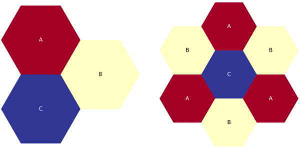
1.3.6. Grids
Grids are described inside a blueprint file using lattice map or grid contents fields to define arrangements in
Hex, Cartesian, or R-Z-Theta. The optional lattice pitch entry allows you to specify spacing between objects that is
different from tight packing. This input is required in mixed geometry cases, for example if Hexagonal assemblies are to
be loaded into a Cartesian arrangement. The contents of a grid may defined using one of the following:
geom:Choose a basic geometry for your lattice: catesian, hex, hex_corners_up, or thetarz.
grid contents:A direct YAML representation of the contents.
lattice map:A ASCII map representing the grid contents.
lattice pitch:The spacing between your lattice point / rows.
symmetry:The default is “full”, but for hexagonal lattices, you have the option of “third periodic”.
Example grid definitions are shown below
grids:
    control:
        geom: hex_corners_up
        symmetry: full
        lattice map: |
           - - - - - - - - - 1 1 1 1 1 1 1 1 1 4
            - - - - - - - - 1 1 1 1 1 1 1 1 1 1 1
             - - - - - - - 1 8 1 1 1 1 1 1 1 1 1 1
              - - - - - - 1 1 1 1 1 1 1 1 1 1 1 1 1
               - - - - - 1 1 1 1 1 1 1 1 1 1 1 1 1 1
                - - - - 1 1 1 1 1 1 1 1 1 1 1 1 1 1 1
                 - - - 1 1 1 1 1 1 1 1 1 1 1 1 1 1 1 1
                  - - 1 1 1 1 1 1 1 1 1 1 1 1 1 1 1 1 1
                   - 1 1 1 1 1 1 1 1 1 1 1 1 1 1 1 1 1 1
                    7 1 1 1 1 1 1 1 1 0 1 1 1 1 1 1 1 1 1
                     1 1 1 1 1 1 1 1 2 1 1 1 1 1 1 1 1 1
                      1 1 1 1 1 1 1 1 1 1 1 1 1 1 1 1 1
                       1 1 1 1 1 1 1 1 1 1 1 1 1 1 1 1
                        1 1 1 1 1 1 1 1 1 1 1 1 1 1 1
                         1 1 1 1 1 1 1 1 1 1 1 1 1 1
                          1 1 1 1 1 1 1 1 1 3 1 1 1
                           1 1 1 1 1 1 1 1 1 1 1 1
                            1 6 1 1 1 1 1 1 1 1 1
                             1 1 1 1 1 1 1 1 1 1
sfp:
    symmetry: full
    geom: cartesian
    lattice pitch:
        x: 50.0
        y: 50.0
    grid contents:
        [0,0]: MC
        [1,0]: MC
        [0,1]: MC
        [1,1]: MC
Tip
Both pin and core grid definitions to share this input.
1.3.6.1. Lattice Maps
One of the features of the ARMI blueprints file is that the user can define a lattice layout of parts of the reactor
using ASCII art (from the asciimaps module). This is meant to help the user define the
layout of assemblies in a reactor core or pins in a block.
The actual syntax is bespoke to ARMI. See the examples below. And note that the whitespace shown is important.
1.3.6.1.1. Full-Core Cartesian Examples
Probably the easiest lattice map to draw using ARMI’s custom ASCII format is a Cartesian grid. Here it is pretty clear how to lay our rows and columns of symbols to represent the grid. Here is a small 6x6 Cartesian map
geom: cartesian
symmetry: full
lattice pitch:
  x: 1.0
  y: 1.0
lattice map: |
  A B B B B B
  A B A A A B
  A B A C A B
  A B B A A B
  A B B B B B
  A A A A A A
Full-core, Cartesian, 6x6 lattice map.
Though ARMI also supports quarter symmtery, which quadruples the grid
geom: cartesian
symmetry: quarter
lattice pitch:
  x: 1.0
  y: 1.0
lattice map: |
  A B B B B B
  A B A A A B
  A B A C A B
  A B B A A B
  A B B B B B
  A A A A A A
Cartesian, 12x12 lattice map, made from quarter symmetry.
1.3.6.1.2. Full-Core Hexagonal Examples
ARMI also supports two types of hexagonal lattices: one with the flat sides of the hexagons pointing up, and one with the corners of the hexagons pointing up.
The more common of the two is the flat-side up, or “flats-up” map
geom: hex
symmetry: full
lattice map: |
    - - E
     - E E
    - E D E
     E D D E
    E D C D E
     D C C D
    E C B C E
     D B B D
    E C A C E
     D B B D
    E C B C E
     D C C D
    E D C D E
     E D D E
      E D E
       E E
        E
Five-ring, full-core, flats-up hexagonal lattice map.
and for a larger example
geom: hex
symmetry: full
lattice map: |
    -   -   -   -   -   -     LC
    -   -   -   -   -   -   LC  LC
      -   -   -   -   -   LC  SH  LC
    -   -   -   -   -   LC  SH  SH  LC
      -   -   -   -   LC  SH  RR  SH  LC
    -   -   -   -   LC  SH  RR  RR  SH  LC
      -   -   -   LC  SH  RR  IC  RR  SH  LC
    -   -   -   LC  SH  RR  IC  IC  RR  SH  LC
      -   -   LC  SH  RR  IC  RR  IC  RR  SH  LC
    -   -   LC  SH  RR  IC  RR  RR  IC  RR  SH  LC
      -   LC  SH  RR  IC  RR  SB  RR  IC  RR  SH  LC
    -   LC  SH  RR  IC  RR  SB  SB  RR  IC  RR  SH  LC
      LC  SH  RR  IC  RR  SB  CA  SB  RR  IC  RR  SH  LC
    -   SH  RR  IC  RR  SB  CA  CA  SB  RR  IC  RR  SH
      LC  RR  IC  RR  SB  CA  SH  CA  SB  RR  IC  RR  LC
    -   SH  IC  RR  SB  CA  SH  SH  CA  SB  RR  IC  SH
      LC  RR  RR  SB  CA  SH  IC  SH  CA  SB  RR  RR  LC
    -   SH  IC  SB  CA  SH  IC  IC  SH  CA  SB  IC  SH
      LC  RR  RR  CA  SH  IC  LC  IC  SH  CA  RR  RR  LC
    -   SH  IC  SB  SH  IC  LC  LC  IC  SH  SB  IC  SH
      LC  RR  RR  CA  IC  LC  SE  LC  IC  CA  RR  RR  LC
    -   SH  IC  SB  SH  LC  SE  SE  LC  SH  SB  IC  SH
      LC  RR  RR  CA  IC  SE  SH  SE  IC  CA  RR  RR  LC
    -   SH  IC  SB  SH  LC  SH  SH  LC  SH  SB  IC  SH
       LC  RR  RR  CA  IC  SE  RR  SE  IC  CA  RR  RR  LC
    -   SH  IC  SB  SH  LC  SH  SH  LC  SH  SB  IC  SH
      LC  RR  RR  CA  IC  SE  SH  SE  IC  CA  RR  RR  LC
    -   SH  IC  SB  SH  LC  SE  SE  LC  SH  SB  IC  SH
      LC  RR  RR  CA  IC  LC  SE  LC  IC  CA  RR  RR  LC
    -   SH  IC  SB  SH  IC  LC  LC  IC  SH  SB  IC  SH
      LC  RR  RR  CA  SH  IC  LC  IC  SH  CA  RR  RR  LC
    -   SH  IC  SB  CA  SH  IC  IC  SH  CA  SB  IC  SH
      LC  RR  RR  SB  CA  SH  IC  SH  CA  SB  RR  RR  LC
    -   SH  IC  RR  SB  CA  SH  SH  CA  SB  RR  IC  SH
      LC  RR  IC  RR  SB  CA  SH  CA  SB  RR  IC  RR  LC
    -   SH  SH  IC  RR  SB  CA  CA  SB  RR  IC  RR  SH
      LC  SH  RR  IC  RR  SB  CA  SB  RR  IC  RR  SH  LC
    -   LC  SH  RR  IC  RR  SB  SB  RR  IC  RR  SH  LC
      -   LC  SH  RR  IC  RR  SB  RR  IC  RR  SH  LC
        -   LC  SH  RR  IC  RR  RR  IC  RR  SH  LC
          -   LC  SH  RR  IC  RR  IC  RR  SH  LC
            -   LC  SH  RR  IC  IC  RR  SH  LC
              -   LC  SH  RR  IC  RR  SH  LC
                -   LC  SH  RR  RR  SH  LC
                  -   LC  SH  RR  SH  LC
                    -   LC  SH  SH  LC
                      -   LC  SH  LC
                        -   LC  LC
                          -   LC
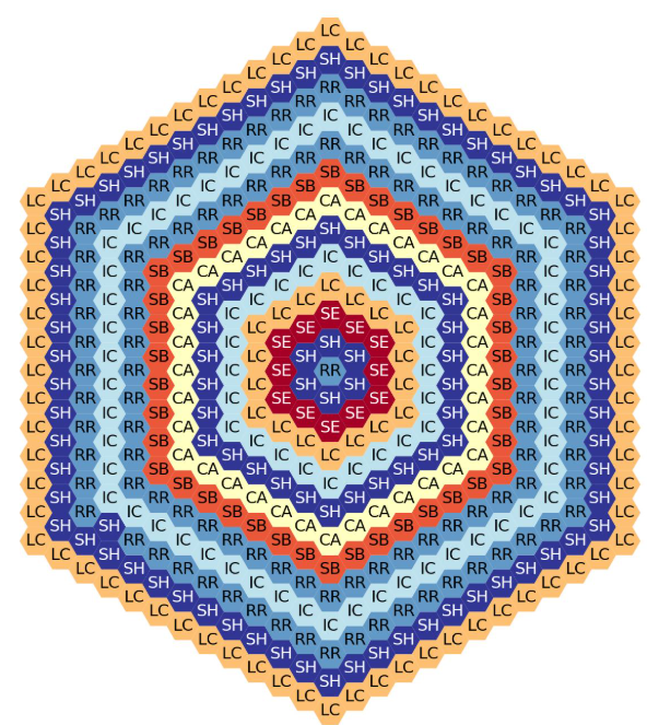
Fourteen-ring, full-core, flats-up hexagonal lattice map.
The other version is the corners up lattice. Notice how the - placeholders are used differently.
geom: hex_corners_up
symmetry: full
lattice map: |
   - - - D D D D
    - - D C C C D
     - D C B B C D
      D C B A B C D
       D C B B C D
        D C C C D
         D D D D
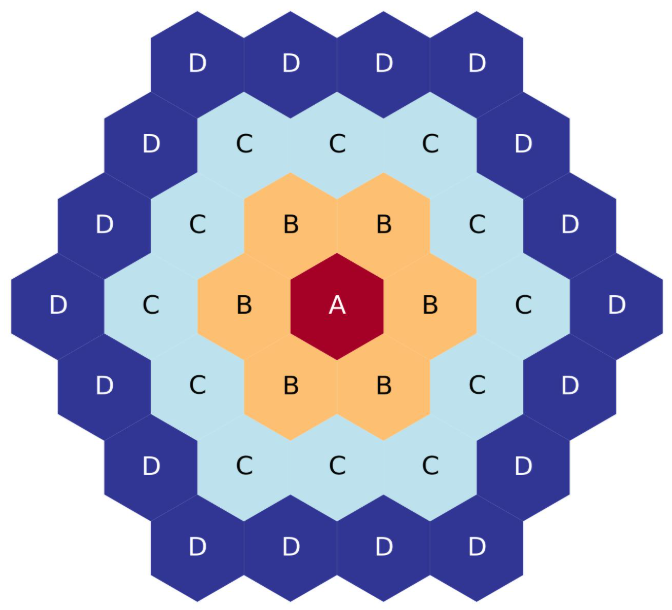
Four-ring, full-core, corners-up hexagonal lattice map.
and a larger example
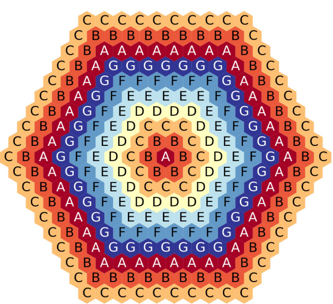
Four-ring, full-core, corners-up hexagonal lattice map.
Tip
If the reactor core is flats-up, then the assembly pins in that core should be corners up. And vice versa.
1.3.6.1.3. Placeholders and Whitespace
In lattice maps whitespace is used to separate symbols. The exact count of spaces is not strictly speaking important; one space is as good as five. The following to lattice maps yield the same result, though obviously one is easier to read than the other
geom: cartesian
symmetry: full
lattice pitch:
  x: 1.0
  y: 1.0
lattice map: |
 C C C C C
 C B B B C
 C B A B C
 C B B B C
 C C C C C
geom: cartesian
symmetry: full
lattice pitch:
  x: 1.0
  y: 1.0
lattice map: |
 C  C      C  C   C
   C  B   B  B   C
       C  B   A  B   C
    C  B   B  B   C
  C C  C    C    C
The - symbol in a lattice map can be used to replace characters with empty space. For instance, above we saw this
geom: hex
symmetry: full
lattice map: |
    - - E
     - E E
    - E D E
     E D D E
    E D C D E
     D C C D
    E C B C E
     D B B D
    E C A C E
     D B B D
    E C B C E
     D C C D
    E D C D E
     E D D E
      E D E
       E E
        E
Five-ring, full-core, flats-up hexagonal lattice map.
But we can replace do some random replacements with - placeholders and get a different result
geom: hex
symmetry: full
lattice map: |
    B B E
     B E E
    B E D E
     E D D E
    E D C D E
     D C C D
    E C - C E
     D - - D
    E C A C E
     D - - D
    E C - C E
     D C C D
    E D C D E
     E D D E
      E D E
       E E
        E
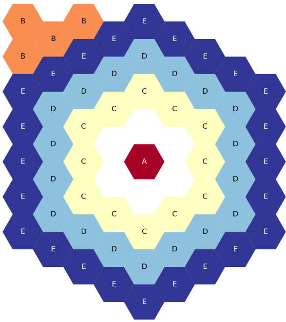
Five-ring, full-core, flats-up hexagonal lattice map. Placeholder fun.
1.3.6.1.4. Two-Ring, Third-Core Hex Maps
There is another kind of lattice map that ARMI supports; third-core lattice maps. These are a special case of hexagonal lattice maps, where instead of drawing out the entire lattice (as above) only one third of the hexagonal lattice is drawn.
This is a common practice in modeling hexagonal reactor cores. To speed up a model run, for a quick study, only one- third of the reactor core is fully modeled, and boundary conditions are set to model this as if it were part of a full reactor core. This only works if the reactor core is exactly symmetric of course.
While this may be a niche case, it is fully supported in ARMI lattice maps, and elsewhere. The only tricky point is that it is not always obvious how to draw the ASCII map to represent these third-core hex grids. To help with that, below are examples of third-core hex grids shown from two rings to eleven. So if you need to make such a lattice map yourself, you should be able to start by copy/pasting the examples below.
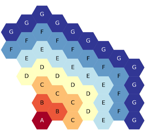
First, let us start with a very simple case; the two-ring hexagonal lattice map. The YAML ASCII map to draw such a lattice is shown below
geom: hex
symmetry: third periodic
lattice map: |
  A
   B
   C
The figure below shows the third-core map plotted out. Also shown is the full-core plotted to represent what an ARMI simulation thinks the entire lattice map looks like, based on the third of the core provided in the ASCII art
Two-ring, third-core, flats-up hexagonal lattice map.
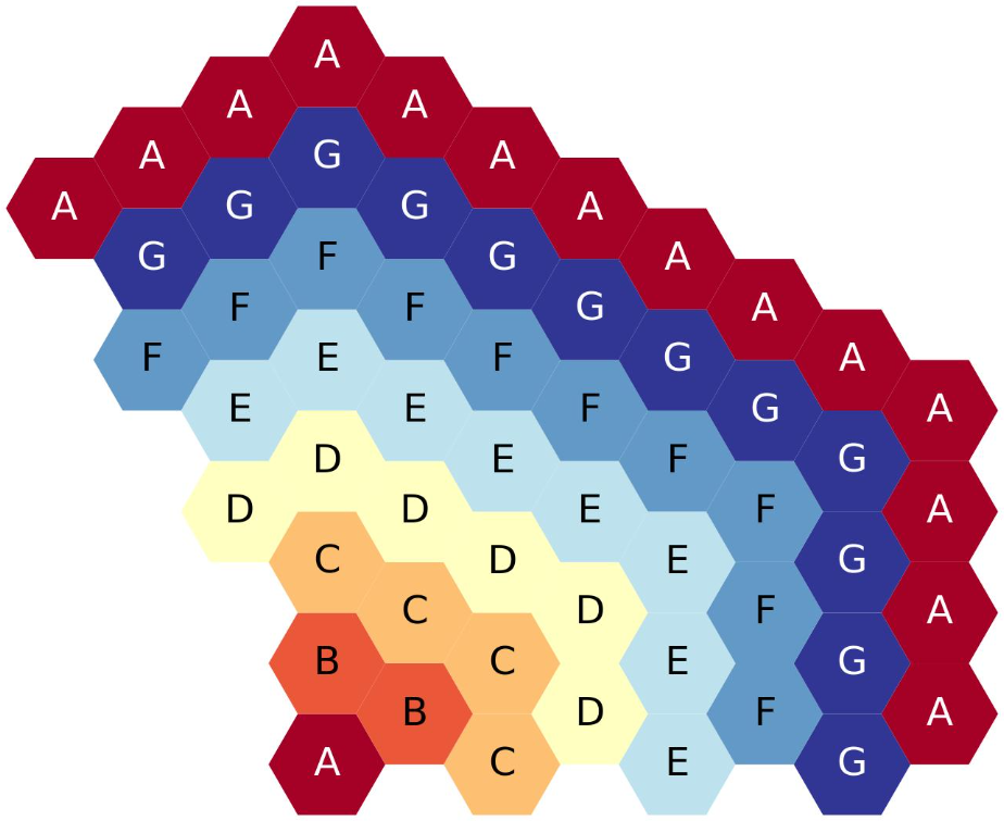
There is another possibility not shown in the example above. A hexagonal grid can be represented with flats or corners
pointing up on the plot. In ARMI, we represent the “corners up” version by specifying a slight change to the geom
field: hex_corners_up as opposed to just hex
geom: hex_corners_up
symmetry: third periodic
lattice map: |
  A
   B
   C
The figure below is a quick plot of the above, corners up version of the two-ring lattice map

Two-ring, third-core, corners-up hexagonal lattice map.
Notice that the two ASCII maps above have three items specified: A, B, and C. The center hex is C and
the others represent the first ring. The full core map shown has seven elements, the center plus six hexagons in the
first ring. So, to calculate the number of hexagons in the full core map from the number of hexagons shown in a third-
core map there is a simple relation
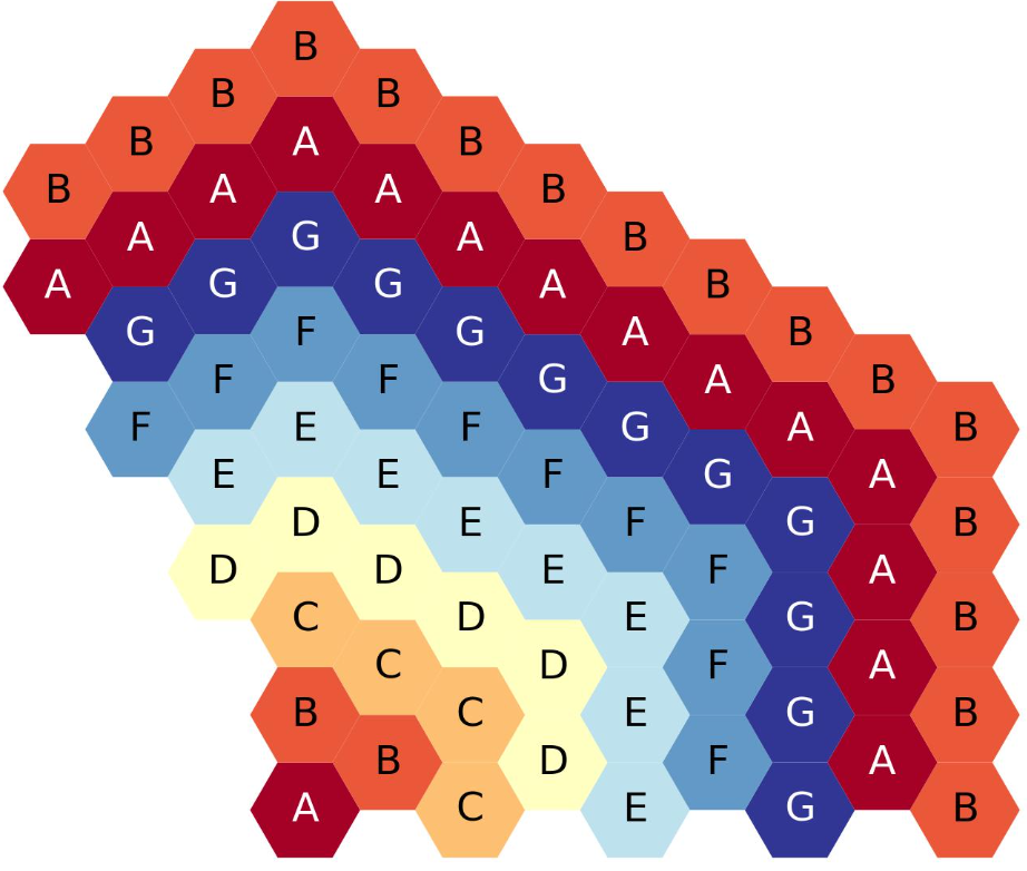
1.3.6.1.5. Three-Ring, Third-Core Hex Maps
Continuing the logical progression, below is an ASCII map of a three-ring, flats-up, third-core hexagonal lattice
geom: hex
symmetry: third periodic
lattice map: |
  D
   E
  A F
   B
  C G
The figure below shows third-core and full-core plots of the above YAML

Three-ring, third-core, flats-up hexagonal lattice map.
And just one more time, let us show the YAML for the corners-up version of the above three-ring lattice
geom: hex_corners_up
symmetry: third periodic
lattice map: |
  D
   E
  A F
   B
  C G
The figure below shows the third-core and full-core plots for the three-ring, corners up lattice

Three-ring, third-core, corners-up hexagonal lattice map.
1.3.6.1.6. Four-Ring, Third-Core Hex Maps
From here on out, the examples will only show the “flats-up” versions of the lattice maps and plots, to reduce duplication.
The four-ring, third-core lattice map is starting to get larger and more complicated than the above examples
geom: hex
symmetry: third periodic
lattice map: |
     D
     D   D
       C   D
         C   D
       B   C
         B   D
       A   C
The figure below shows a plot of the above four-ring example. If you are copying from this example, please note that each ring is filled with a different letter. Hopefully this makes your translation easier.
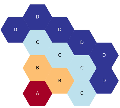
Four-ring, third-core, flats up hexagonal lattice map.
1.3.6.1.7. Five-Ring, Third-Core Hex Maps
Five-ring and above ASCII maps start to require the placeholder - character. This does not represent a hexagon, but
is just a piece of cruft to help lay out larger ASCII maps
geom: hex
symmetry: third periodic
lattice map: |
     -   E
       E   E
         D   E
       D   D   E
         C   D   E
           C   D
         B   C   E
           B   D
         A   C   E
The next figure shows a plot of the five-ring, third core lattice map above. Again, each hexagonal ring is filled with a different letter / symbol, to hopefully help make the map more clear.
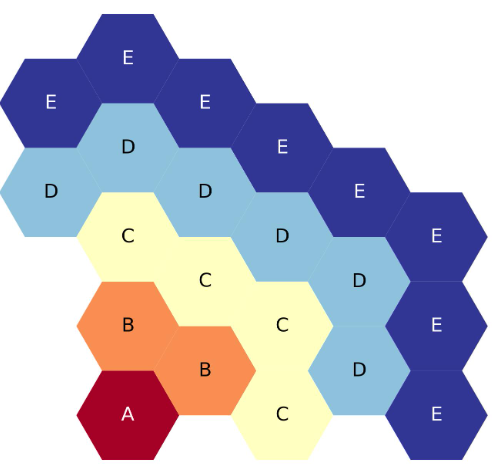
Five-ring, third-core, flats up hexagonal lattice map.
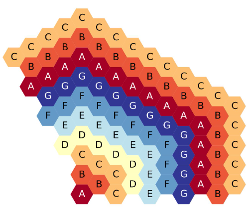
1.3.6.1.8. Six-Ring, Third-Core Hex Maps
From six-rings and up, the third-core lattice maps start to look a lot more similar to each other. There is a noticable pattern emerging that should make it easier to add or remove one hexagonal ring from the map
geom: hex
symmetry: third periodic
lattice map: |
    -    F
       F   F
     F   E   F
       E   E   F
         D   E   F
       D   D   E   F
         C   D   E
           C   D   F
         B   C   E
           B   D   F
         A   C   E
The figure below shows the six-ring, third-core, flats-up, hexagonal lattice map, with each ring filled with a different symbol for clarity.
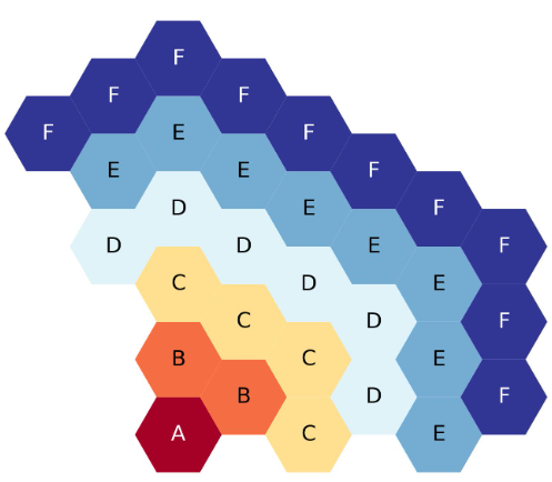
Six-ring, third-core, flats up hexagonal lattice map.
1.3.6.1.9. Seven-Ring, Third-Core Hex Maps
The seven-ring map looks much like the six-ring map, exact we have added a new ring filled with G symbols. And from
here on out, even extra ring added to the map requires adding exactly one more placeholder - symbol, to correctly
space out the ASCII letters and make them more readable
geom: hex
symmetry: third periodic
lattice map: |
   -     G
   -   G   G
     G   F   G
       F   F   G
     F   E   F   G
       E   E   F   G
         D   E   F   G
       D   D   E   F
         C   D   E   G
           C   D   F
         B   C   E   G
           B   D   F
         A   C   E   G
The next figure shows the seven-ring, third-core, flats-up hexagonal lattice map, each ring filled with a different symbol.
Seven-ring, third-core, flats up hexagonal lattice map.
1.3.6.1.10. Eight-Ring, Third-Core Hex Maps
The YAML for an eight-ring third core lattice map looks much the same as the seven-ring above. But notice the new ring
added has been filled with A symbols and one more - placeholder was added.
geom: hex
symmetry: third periodic
lattice map: |
   -  -   A
   -    A   A
      A   G   A
    A   G   G   A
      G   F   G   A
        F   F   G   A
      F   E   F   G   A
        E   E   F   G   A
          D   E   F   G
        D   D   E   F   A
          C   D   E   G
            C   D   F   A
          B   C   E   G
            B   D   F   A
          A   C   E   G
The figure below shows the eight-ring, third-core, flats-up hexagonal lattice map, each ring filled with a different symbol.
Eight-ring, third-core, flats up hexagonal lattice map.
1.3.6.1.11. Nine-Ring, Third-Core Hex Maps
The nine-ring lattice map below looks much like the eight ring above. The new ring has been filled with B symbols
and one more - placeholder has been added.
geom: hex
symmetry: third periodic
lattice map: |
  -  -        B
  -         B   B
  -       B   A   B
        B   A   A   B
          A   G   A   B
        A   G   G   A   B
          G   F   G   A   B
        F   F   G   A   B
      F   E   F   G   A   B
        E   E   F   G   A
          D   E   F   G   B
        D   D   E   F   A
          C   D   E   G   B
            C   D   F   A
          B   C   E   G   B
            B   D   F   A
          A   C   E   G   B
The figure below shows the nine-ring, third-core, flats-up hexagonal lattice map, each ring filled with a different symbol.
Nine-ring, third-core, flats up hexagonal lattice map.
1.3.6.1.12. Ten-Ring, Third-Core Hex Maps
Below is the YAML representing a ten-ring, third core, hexagonal lattice map. A new ring filled with C has been
added to the nine-ring lattice map above and one more - placeholder has been added.
geom: hex
symmetry: third periodic
lattice map: |
  -  -     C
  -  -   C   C
  -    C   B   C
     C   B   B   C
   C   B   A   B   C
     B   A   A   B   C
       A   G   A   B   C
     A   G   G   A   B   C
       G   F   G   A   B   C
         F   F   G   A   B   C
       F   E   F   G   A   B
         E   E   F   G   A   C
           D   E   F   G   B
         D   D   E   F   A   C
           C   D   E   G   B
             C   D   F   A   C
           B   C   E   G   B
             B   D   F   A   C
           A   C   E   G   B
The figure below shows the 10-ring, third-core, flats-up hexagonal lattice, each ring filled with a different symbol.
Ten-ring, third-core, flats up hexagonal lattice map.
1.3.6.1.13. Eleven-Ring, Third-Core Hex Maps
Below is the YAML representing a eleven-ring, third core, hexagonal lattice map. A new ring filled with D has been
added to the eleven-ring lattice map above and one more - placeholder has been added.
geom: hex
symmetry: third periodic
lattice map: |
  -  -  -  D
  -  -   D   D
  -    D   C   D
  -  D   C   C   D
   D   C   B   C   D
     C   B   B   C   D
   C   B   A   B   C   D
     B   A   A   B   C   D
       A   G   A   B   C   D
     A   G   G   A   B   C   D
       G   F   G   A   B   C   D
         F   F   G   A   B   C
       F   E   F   G   A   B   D
         E   E   F   G   A   C
           D   E   F   G   B   D
         D   D   E   F   A   C
           C   D   E   G   B   D
             C   D   F   A   C
           B   C   E   G   B   D
             B   D   F   A   C
           A   C   E   G   B   D
The figure below shows the eleven-ring, third-core, flats-up hexagonal lattice map, each ring filled with a different symbol.
Eleven-ring, third-core, flats up hexagonal lattice map.
This same logic of adding a new ring to the ASCII representation of the lattice map can be used to create arbitrarily large third-core, hexagonal lattice maps. However, we will stop at 11 rings because we have to stop somewhere.
1.3.7. Custom Isotopics
In some cases (such as benchmarking a previous reactor), the default mass fractions from the material library are not
what you want to model. In these cases, you may override the isotopic composition provided by the material library in
this section. There are three ways to specify the isotopics: mass fractions (sum to 1.0), number densities (in
atoms/barn-cm), or number fractions (sum to 1.0). For example:
custom isotopics:
    LABEL1:
        input format: mass fractions
        density: 7.79213903298633
        C: 0.000664847887388523
        CR: 0.182466356404319
        CU: 0.00323253628006144
        FE: 0.705266053783901
        MN: 0.0171714161260001
        MO: 0.00233843050046998
        NI: 0.0831976890804466
        SI: 0.00566266993741259
See the List of Nuclides for all valid entries. Note that ARMI will expand
elemental nuclides to their natural isotopics in most cases (to correspond with the nuclear data library).
The (mass) density input is invalid when specifying number densities; the code will present an error message.
Material density may be specified in custom isotopics either explicitly in a mass fractions input format (shown
above) or implicitly with number densities. This is fairly straightforward for the Custom material, as it has no
baseline density. Density may also be specified for components using materials which have entries in the materials
library. Users should be aware of the following interactions when specifying a custom density for components using a
library material:
1. The library material density will not be changed. Only the component(s) with the custom isotopics entry will have the density modification.
2. Density specified by custom isotopics will override all other density modifications in the component construction phase (e.g.
TD_fracentries).3. Only the component density is changed, not other material properties are altered to account for the change in composition/density.
4. Density can only be specified using custom isotopics for non-
Custommaterials that have some initial density. Don’t try to makeVoidhave mass!
Densities specified using Custom Isotopics are applied in component construction, and should be specified at the
input temperature for the component. Note that when overriding the density of a library material, all other properties
of that material (e.g. expansion coefficients) will continue to be used as if the component consisted of the library
material. In other words, ARMI will still think the component is made out of the original material!
1.3.8. Advanced topics
1.3.8.1. Overlapping shapes
Solids of different compositions in contact with each other present complications during thermal expansion. The ARMI
Framework does not perform calculations to see exactly how such scenarios will behave mechanically; it instead focuses
on conserving mass. To do this, users should input a zero-dimension component linking the 2 solid components made of the
special Void material. This gap will allow the 2 components to thermally expand independently while keeping track of
the overlapping area.
It is important to keep track of the areas when a DerivedShape is included in a block design because ARMI calculates the
derived area by taking the full area of the block and subtracting the total area of the non-DerivedShapes. If area
between thermally-expanding solids was not accounted for, this would non-physically add or subtract coolant into these
gaps. To model overlapping components heterogeneously, it is suggested to use a
block converter.
Additionally, it should be noted that assigning mult: fuel.mult will be ever-so-slightly slower than just defining
the actual value. This is because ARMI needs to find the sibling component and get the siblings mult. If you are
concerned about performance at that level and don’t expect mult to change much in your case, you can replace the
constant link (i.e. it does not change over time) with a YAML anchor and alias.
1.3.8.2. Component area modifications
In some scenarios, it is desired to have one component’s area be subtracted or added to another. For example, the area
of the skids in a skid duct design needs to be subtracted from the interstitial coolant. The mechanism to handle this
involves adding a parameter to the component to be modified after all the required ones in the form of
<componentName>.add or <componentName>.sub. The component to be added or subtracted must be defined before the
component that is being modified. This allows fairly complicated configurations to be modeled without explicitly
defining new components.
blocks:
    rect with 100 holes:
        holes:
            shape: Circle
            material: Sodium
            Tinput: 600
            Thot: 600
            mult: 100
            od: 0.05
        square of steel:
            shape: Square
            material: Iron
            Tinput: 25.0
            Thot: 600.0
            widthOuter: 3.0
            modArea: holes.sub  # "holes" is the name of the other component
1.3.8.3. Putting it all together to make a Block
Here is a complete fuel block definition:
blocks:
    fuel: &block_fuel
        bond:
            shape: Circle
            material: Sodium
            Tinput: 450.0
            Thot: 450.0
            id: fuel.od
            mult: fuel.mult
            od: cladding.id
        clad:
            shape: Circle
            material: HT9
            Tinput: 25.0
            Thot: 450.0
            id: 0.905
            mult: fuel.mult
            od: 1.045
        coolant:
            shape: DerivedShape
            material: Sodium
            Tinput: 450.0
            Thot: 450.0
        duct:
            shape: Hexagon
            material: HT9
            Tinput: 25.0
            Thot: 450.0
            ip: 15.2
            mult: 1.0
            op: 16.2
        fuel:
            shape: Circle
            material: UZr
            Tinput: 25.0
            Thot: 600.0
            id: 0.0
            isotopics: LABEL1
            mult: 169.0
            od: 0.757
        intercoolant:
            shape: Hexagon
            material: Sodium
            Tinput: 450.0
            Thot: 450.0
            ip: duct.op
            mult: 1.0
            op: 16.79
        wire:
            shape: Helix
            material: HT9
            Tinput: 25.0
            Thot: 450.0
            axialPitch: 30.0
            helixDiameter: 1.145
            id: 0.0
            mult: fuel.mult
            od: 0.1
1.3.8.4. Making blocks with unshaped components
Sometimes you will want to make a homogeneous block, which is a mixture of multiple materials, and will not want to define an exact shape for each of the components in the block. In this case unshaped components can be used, but ARMI still requires there to be at least one component with shape to define the pitch of the block.
In the example below, the block is a rectangular pitch so one of the components is defined as a rectangle to indicate this. Its outer dimensions determine the pitch of the block. The inner dimensions can be whatever is necessary to preserve the area fraction. Note that rectangular blocks have pitch defined by two numbers, since they may not be a square. In this case the rectangle component is half the area fraction and the other two components are one quarter:
blocks:
    fuel:
        clad:
            shape: Rectangle
            material: HT9
            Tinput: 25.0
            Thot: 25.0
            lengthOuter: 3.0
            lengthInner: 2.4
            widthOuter: 2.0
            widthInner: 1.25
            mult:1.0
        fuel:
            shape: UnshapedComponent
            material: UZr
            Tinput: 25.0
            Thot: 25.0
            area = 1.5
        coolant:
            shape: UnshapedComponent
            material: Sodium
            Tinput: 25.0
            Thot: 25.0
            area = 1.5
Warning
When using this method avoid thermal expansion by setting TInput=THot, or your pitch component dimensions might change, thus changing your pitch.
Alternatively, a void (empty) component with zero area can be added for defining the pitch, and then all three components can be defined as unshaped. The downside, is there are now four components, but only three that have actual area and composition:
blocks:
    fuel:
        clad:
            shape: UnshapedComponent
            material: HT9
            Tinput: 25.0
            Thot: 25.0
            area: 3.0
        fuel:
            shape: UnshapedComponent
            material: UZr
            Tinput: 25.0
            Thot: 25.0
            area = 1.5
        coolant:
            shape: UnshapedComponent
            material: Sodium
            Tinput: 25.0
            Thot: 25.0
            area = 1.5
        PitchDefiningComponent:
            shape: Rectangle
            material: Void
            lengthOuter: 3.0
            lengthInner: 3.0
            widthOuter: 2.0
            widthInner: 2.0
            mult:1.0
This can similarly be done for hex geometry and and a hexagon with Outer Pitch (op).
Warning
The rest of the input described below are scheduled to be moved into the settings input file, since their nature is that of a setting.
1.3.9. Nuclide Flags
The nuclide flags setting allows the user to choose which nuclides they would like to consider in the problem, and
whether or not each nuclide should transmute and decay. For example, sometimes you may not want to deplete trace
elements in structural materials, but in other analysis you might. If the nuclide should deplete, it must have
burn: true. If it is to be included in the problem at all, it must be have xs: true All nuclides that will be
produced via transmutation/decay must also have burn: true, so if you add Thorium, make sure to add all other
actinides in its chain. You can use the expandTo: section to list a subset of natural nuclides to expand into. If
you leave this section out, a default set of nuclide flags will be applied to your problem. Remember this section when
you start changing which nuclides are modeled and which ones deplete.:
# this is a YAML comment
nuclide flags:
    AL: {burn: false, xs: true}
    AM241: {burn: true, xs: true}
    C: &carbon_flags {burn: false, xs: true}  # an anchor to "carbon_flags"
    CA: *carbon_flags
    CL: *carbon_flags
    CO: *carbon_flags                         # the alias back to "carbon_flags"
    CR: *carbon_flags
    CU: *carbon_flags
    FE: *carbon_flags
    H: {burn: false, xs: true}
    MN: {burn: false, xs: true}
    MO: {burn: false, xs: true}
    N: {burn: false, xs: true}
    NA: {burn: false, xs: true}
    NI: {burn: false, xs: true}
    O: {burn: false, xs: true, expandTo: ["O16", "O17"]}
    P: {burn: false, xs: true}
    PU238: {burn: true, xs: true}
    PU239: {burn: true, xs: true}
    PU240: {burn: true, xs: true}
    PU241: {burn: true, xs: true}
    PU242: {burn: true, xs: true}
    S: {burn: false, xs: true}
    SI: {burn: false, xs: true}
    U234: {burn: false, xs: true}
    U235: {burn: true, xs: true}
    U236: {burn: true, xs: true}
    U238: {burn: true, xs: true}
The code will crash if materials used in Blocks and Components contain nuclides not defined in nuclide flags.
A failure can also occur if the burn chain is missing a nuclide.
Tip
We plan to upgrade the default behavior of this to inherit from all defined materials in a problem to reduce the user-input burden.
1.4. The Materials Input File
The materials input files define materials to be used during an ARMI-based simulation. The YAML data format below is
the preferred way to define materials in ARMI, and they are loaded by the armi.matProps package. However, for
increased flexiblity, the armi.materials package allows users to define materials entirely in Python, without
dealing with the below YAML data format. Please see the armi.materials.material.Material class for more information.
You can find example YAML material files under armi/resources/materials/ and example Python materials under:
armi/materials/.
This YAML material file format is human readable, hierarchical, and compact. The base name of the YAML filename (the
file name without the file path or extension suffix) is interpreted by matProps as the case-sensitive material name.
The extension for the material data file must be one of these: .yaml, .yml, .YAML, or .YML.
Below is an example material data file containing all the basic matProps concepts, discussed in the following sections.
file format: 3.0
material type: Metal
composition:
    C: [0.17, 0.23]
    P: [0.0, 0.040]
    Cr: [11.0, 12.5]
    Fe: balance
references:
    - ref: reference citation 1
      type: open literature
    - ref: reference citation 2
      type: open literature

Young's modulus:
    function:
        T:
            min: 0
            max: 700
        type: symbolic
        equation: 1.100E+11 - 1.200E+07 - 1.300E+03 * T**2
    tabulated data:
        - [  0, 1.100E+11]
        - [200, 1.075E+11]
        - [400, 1.050E+11]
        - [600, 1.023E+11]
        - [700, 1.010E+11]

density:
    tabulated data: &tagged_data
        - [ 20, 1.088E-05]
        - [200, 1.215E-05]
        - [400, 1.316E-05]
        - [600, 1.369E-05]
        - [800, 1.576E-05]
    function:
        T:
            min: 20
            max: 800
        type: piecewise
        functions:
            - function:
                T: 0
                type: table
                tabulated data: *tagged_data
            - function:
                T:
                    min: 602
                    max: 800
                type: symbolic
                equation: 2.1e8 - 2.2E8 * tanh((T-550.0)/180.0)
Poisson's ratio:
    function:
        T:
            min: -273
            max: 5000
        type: symbolic
        equation: 0.321

yield strength:
    function:
        T:
            min: 350
            max: 500
        D:
            min: 0
            max: 100
        type: symbolic
        equation: 400.0 * T**2.0 + D

stress to rupture:
    function:
        T: 0
        t: 1
        type: two dimensional table
    tabulated data:
      - [null,    [   100.,    200.,    300.]]
      - [1000.,   [123.456, 23456.7, 456.789]]
      - [10000.,  [78910.1, 89.0123, 10111.2]]

design fatigue strain range:
    function:
        T: 0
        n: 1
        type: two dimensional table
    tabulated data:
        - [null,     [  427.,   600.,   775.,   800.]]
        - [10.,      [  0.012, 0.0059,0.0036, 0.0029]]
        - [20.,      [  0.01,  0.0051,0.0033, 0.0020]]
The only required entries in a material file are file format, composition, and material type.
1.4.1. File Format
The file format: version field defines the file format version. This is a required field. This version string is
verified to see if it is supported for use by matProps.
1.4.2. Material Type
The material type field defines the type of material. Valid values for this key include Metal, Fuel, Fluid, Ceramic,
ASME2015, ASME2017, SimpleSolid, and Composite. This is a required field. This field is meant to provide information to
the user and is not used by matProps, though it may be used by downstream codes.
1.4.3. Composition
The composition field defines the chemical composition of the material. This is a required field. The value for this
field is a collection of key-value pairs, as denoted by indentation. The key is an element name, and the value is a list
of length 2 that defines the minimum percent composition then the maximum percent composition for the element. There
must be one and only one element listed as “balance” instead of a pair of minimum and maximum values. The “balance”
element will fill any remaining fraction of the elements composition, to get the total to 100 percent.
Optionally, this data entry can be associated with a references keyword.
Composition Requirements:
The value “balance” shall be assigned to one and only one element.
The sum of the mean of the percent composition range for non-trace elements (elements with a minimum composition of 0) shall not exceed 100.
1.4.4. Properties
The property field defines a property of the material. This is usually a temperature-dependent curve describing the
material, like density. The value for this field is a collection consisting of several required and optional keywords. A
summary of the keywords, their relevant status and appropriate section can be found below.
Property Components |
Required Status |
Section |
|---|---|---|
function |
Required |
|
references |
Optional |
|
tabulated data |
Required for table data functions. Otherwise, it is optional. |
|
The table below lists the default collection of properties that are defined for a material by matProps. Note that
these property names are case sensitive.
Material Property YAML Name |
API Name |
|---|---|
thermal diffusivity |
|
instantaneous coefficient of thermal expansion |
|
mean coefficient of thermal expansion |
|
specific heat capacity |
|
Young’s modulus |
|
shear modulus |
|
thermal conductivity |
|
dynamic viscosity |
|
kinematic viscosity |
|
Poisson’s ratio |
|
elongation |
|
density |
|
allowable stress |
|
design stress |
|
service reference stress |
|
design reference stress |
|
stress to rupture |
|
time dependent design stress |
|
tensile strength |
|
yield strength |
|
allowable time to rupture |
|
allowable time to allowable stress |
|
tensile strength reduction factor |
|
yield strength reduction factor |
|
weld strength reduction factor |
|
design fatigue strain range |
|
strain from isochronous stress-strain curve |
|
design fatigue stress |
|
surface tension |
|
electrical conductance |
|
vapor pressure |
|
isothermal compressibility |
|
melting temperature |
|
boiling temperature |
|
linear expansion |
|
vapor specific volume |
|
speed of sound |
|
solidus temperature |
|
liquidus temperature |
|
volumetric expansion |
|
enthalpy |
|
temperature from enthalpy |
|
enthalpy of fusion |
|
latent heat of vaporization |
|
fracture toughness |
|
Brinell Hardness |
|
factor f from ASME.III.5 Fig. HBB-T-1432-2 |
|
factor Kv’ from ASME.III.5 Fig. HBB-T-1432-3 |
|
It is quite easy to add another material property to your simulation. Use the defProp function, and describe the new
property by: short name, long name, and units. It will then be available to use in your material YAML files like any
other property.
from armi.matProps.prop import defProp

defProp("fuzz", "fuzziness", "1/m^2")
defProp("goo", "gooiness", "m^2/s")
defProp("squish", "squishiness", "1/Pa")

armi.matProps.loadSafe("/pop/six/squish/uhuh/cicero/lipschitz")
1.4.5. Tabulated Data
A material property can be defined not just by math, but by tabulated data. This is flexible, easy to use, and can
better match laboratory measurements. Currently, matProps supports one dimensional and two dimensional tables of
data, as shown in the example at the beginning of this section. Notice that the type field is used to make this
distinction.
These tables of data can be large and inconvienent to duplicate. So you can tag and name the tables of data for use
elsewhere in the YAML file. (Look for "tabulated data: &tagged_data" in the example file above.)
1.4.6. Functions
The function field allows the developer to define a mathematical curve for a material property. For instance, in the
example file above, a function is used to represent the “Young’s modulus” of the material. The independent variable “T”
is defined to represent Temperature in degrees C, and the min and max values of 0 and 700 are given. This defines the
valid bounds upon which the polynomial “equation” can be evaluated.
The function system is very flexible though. Notice that “Poisson’s ratio” above has "equation: 0.321", so constant
functions are easy to define. And “yield strength” is actually a function of two independent variables, which
matProps supports. Functions can also include tabular data. For tabular functions, instead of child keys, the value
0 or 1 is provided to indicate which dimension of the table corresponds to which variable. Values returned from
tabular functions will be interpreted from the provided values. Several other types of functions are defined in detail
below.
Like most everything else in a matProps YAML file, this field can (and probably should) also include a list of
references to properly attribute the source of the data.
1.4.7. Symbolic
A symbolic function is defined by supplying value symbolic for the key type. Symbolic functions may use any
number of independent variables. The equation node must be supplied which contains a string with the equation
function. The symbolicOperators field defines the set of operators that may be used in the symbolic equation
string. These operators may be combined in any order to build a symbolic expression. While other operators outside of
the table might function in matProps, they are untested and may not be used in qualified scope.
Note
Both operators and variables are case sensitive.
Note
Implicit multiplication will result in a Value Error. The multiplication operator must be used.
Operator |
Definition |
|---|---|
* |
Multiplication |
** |
Exponent |
/ |
Division |
+ |
Addition |
- |
Subtraction |
( ) |
Grouping symbol |
sin |
Sine |
cos |
Cosine |
tan |
Tangent |
sinh |
Hyperbolic Sine |
cosh |
Hyperbolic Cosine |
tanh |
Hyperbolic Tangent |
ln |
Natural Logarithm |
log |
|
log10 |
Base 10 Logarithm |
exp |
Exponential (base e) |
e or E |
Scientific Notation |
1.4.8. Table
Providing table for the type key indicates a one dimensional tables that uses interpolation. This function type
requires a set of tabulated data to be defined in the collection. The set of tabulated data is a list of lists of length
2 with the first element being the independent variable, and the second element being the property value at that
independent variable value.
1.4.9. Piecewise
Using the piecewise keyword allows multiple functions to be defined for different ranges of independent variable
values. As in the density example above, the field functions is used to define a list of functions, one for each
range defined.
Note
While piecewise-defined functions are allowed to have gaps in the valid range between child functions, the child function valid regions may not overlap. An error will be raised during parsing the set of child functions have overlapping valid ranges or utilize different independent variables.
Note
If the piecewise-defined function is discontinuous at a point (two child functions overlap at a point), the function that is defined first in the input file will be used.
1.4.10. Two Dimensional Table
The two dimensional table field defines a two-dimensional table, that needs to be supplied a specially formatted
data set. See the “stress to rupture” property in the above example file. This can again use the tagged data system to
share data with other fields, see "&tagged_data" in the above example file.
The form of the inner lists varies depending on whether the list corresponds to the first row or one of the subsequent
rows. The first row will always have its first entry be a None value. The second value will be a list containing all
of the values for the first independent variable (indicated by 0 in the independent variable node), in ascending
order, that are utilized in the two-dimensional table. Each subsequent row will have its first entry be the second
independent variable value corresponding to that row. The second entry will be the property values that map to the
independent variable combination for that row and column. The size of the lists in the second entry must be consistent
for each row. If there is a property value that does not exist for an independent variable combination, then a value of
None must be specified in its place. If the point including None is used in evaluation, an error will be raised.
1.4.11. Troubleshooting
The armi.matProps package includes error checking to avoid invalid states or returning inaccurate data. Any error
found raises an Exception that includes a helpful message. The four broad categories of matProps errors are:
Invalid file format
Failed node value check
Property evaluation problem
Problem loading or retrieving material data
The first two categories of problems are formatting errors or invalid values in the material YAML file. These problems can only be resolved by making an edit to the material YAML file. Property evaluation issues arise from users providing invalid input to property functions. For instance, if the density is requested outside the defined valid range of temperatures. Finally, problems loading or retrieving material data usually arise by trying to either load a material file (or directory) that does not exist or by an attempted overwrite of a material that has already been saved.
1.5. Fuel Management Input
Fuel management in ARMI is specified through custom Python scripts or YAML files that often reside in the working directory of a run (but can be anywhere if you use full paths). During a normal run, ARMI checks for several fuel management settings:
shuffleLogicThe path to the Python source file or dotted import path to a module that contains the user’s custom fuel management logic
shuffleSequenceFileThe path to a yaml file containing the user’s custom fuel management logic.
fuelHandlerNameThe name of a FuelHandler class that ARMI will look for in the Fuel Management Input module or file specified by
shuffleLogic. Since it’s input, it’s the user’s responsibility to design and place that object in that module or file.
Note
We consider the limited syntax needed to express fuel management in Python code itself to be sufficiently expressive and simple for non-programmers to actually use. Also, fuel management options are available through YAML input files.
The ARMI Operator will call its fuel handler’s outage method before each cycle (and, if requested, during branch
search calculations). The outage() method will perform
bookkeeping operations, and eventually call the user-defined chooseSwaps method (located in Fuel Management Input).
chooseSwaps will generally contain calls to
findAssembly(),
swapAssemblies() ,
swapCascade(), and
dischargeSwap(), which are the primary
fuel management operations and can be found in the fuel management module.
Also found in the user-defined Fuel Management Input module is a getFactors method, which is used to control which
shuffling routines get called and at which time.
Note
See the fuelHandlers module for more details.
1.5.1. Fuel Management Operations
In the ARMI, the assemblies can be moved as units around the reactor with swapAssemblies, dischargeSwap, and swapCascade
of a FuelHandler interface.
1.5.1.1. swapAssemblies
swapAssemblies is the simplest fuel management operation. Given two assembly objects, this method will switch their locations.
self.swapAssemblies(a1,a2)
1.5.1.2. dischargeSwap
A discharge swap is a simple operation that puts a new assembly into the reactor while discharging an outgoing one.
self.dischargeSwap(newIncoming,oldOutgoing)
This operation keeps track of the outgoing assembly in a SpentFuelPool object that the Reactor object has access to so you can see how much of what you discharged.
1.5.1.3. swapCascade
SwapCascade is a more powerful swapping function that can swap a list of assemblies in a “daisy-chain” type of operation. These are useful for doing the main overtone shuffling operations such as convergent shuffling and/or convergent-divergent shuffling. If we load up the list of assemblies, the first one will be put in the last one’s position, and all others will shift accordingly.
As an example, consider assemblies 1 through 5 in core positions A through E.:
self.swapCascade([a1,a2,a3,a4,a5])
This table shows the positions of the assemblies before and after the swap cascade.
Assembly |
Position Before Swap Cascade |
Position After Swap Cascade |
|---|---|---|
1 |
A |
E |
2 |
B |
A |
3 |
C |
B |
4 |
D |
C |
5 |
E |
D |
Arbitrarily complex cascades can thusly be assembled by choosing the order of the assemblies passed into swapCascade.
1.5.2. Choosing Assemblies to Move
The methods described in the previous section require known assemblies to shuffle. Choosing these assemblies is
the essence of fuel shuffling design. The single method used for these purposes is the FuelHandler’s findAssembly
method. This method is very general purpose, and ranks in the top 3 most important methods of the ARMI altogether.
To use it, just say:
a = self.findAssembly(param='maxPercentBu',compareTo=20)
This will return the assembly in the reactor that has a maximum burnup closest to 20%. Other inputs to findAssembly are
summarized in the API docs of findAssembly().
1.5.3. Fuel Management Examples
1.5.3.1. Convergent-Divergent
Convergent-divergent shuffling is when fresh assemblies march in from the outside until they approach the jump ring, at which point they jump to the center and diverge until they reach the jump ring again, where they now jump to the outer periphery of the core, or become discharged.
If the jump ring is 6, the order of target rings is:
[6, 5, 4, 3, 2, 1, 6, 7, 8, 9, 10, 11, 12, 13]
In this case, assemblies converge from ring 13 to 12, to 11, to 10, …, to 6, and then jump to 1 and diverge until they get back to 6. In a discharging equilibrium case, the highest burned assembly in the jumpRing should get discharged and the lowest should jump by calling a dischargeSwap on cascade[0] and a fresh feed after this cascade is run.
The convergent rings in this case are 7 through 13 and the divergent ones are 1 through 5 are the divergent ones.
1.5.4. Fuel Management Tips
Some mistakes are common. Follow these tips.
Always make sure your assembly-level types in the settings file are up to date with the grids in your bluepints file. Otherwise you’ll be moving feeds when you want to move igniters, or something.
Use the exclusions list! If you move a cascade and then the next cascade tries to run, it will choose your newly-moved assemblies if they fit your criteria in
findAssemblies. This leads to very confusing results. Therefore, once you move assemblies, you should default to adding them to the exclusions list.Print cascades during debugging. After you’ve built a cascade to swap, print it out and check the locations and types of each assembly in it. Is it what you want?
1.5.5. Running a branch search
ARMI can perform a branch search where a number of fuel management operations are performed in parallel and the preferred one is chosen and proceeded with. The key to any branch search is writing a fuel handler that can interpret fuel management factors, defined as keyed values between 0 and 1.
As an example, a fuel handler may be written to interpret two factors, numDischarges and chargeEnrich. One
method in the fuel handler would then take the value of factors['numDischarges'] and multiply it by the maximum
number of discharges (often set by another user setting) and then discharge this many assemblies. Similarly, another
method would take the factors['chargeEnrich'] value (between 0 and 1) and multiply it by the maximum allowable
enrichment (again, usually controlled by a user setting) to determine which enrichment should be used to fabricate new
assemblies.
Given a fuel handler that can thusly interpret factors between 0 and 1, the concept of branch searches is simple. They simply build uniformly distributed lists between 0 and 1 across however many CPUs are available and cases on all of them, passing one of each of the factors to each CPU in parallel. When the cases finish, the branch search determines the optimal result and selects the corresponding value of the factor to proceed.
Branch searches are controlled by custom getFactorList methods specified in the shuffleLogic input modules or
files. This method should return two things:
A
defaultFactors; a dictionary with user-defined keys and values between 0 and 1 for each key. These factors will be passed to thechooseSwapsmethod, which is typically overridden by the user in custom fuel handling code. The fuel handling code should interpret the values and move the fuel according to what is sent.A
factorSearchFlagslist, which lists the keys to be branch searched. The search will optimize the first key first, and then do a second pass on the second key, holding the optimal first value constant, and so on.
Such a method may look like this:
def getFactorList(cycle,cs=None):

    # init default shuffling factors
    defaultFactors = {'chargeEnrich':0,'numDischarges':1}
    factorSearchFlags=[] # init factors to run branch searches on

    # determine when to activate various factors / searches
    if cycle not in [0,5,6]:
        # shuffling happens before neutronics so skip the first cycle.
        defaultFactors['chargeEnrich']=1
    else:
        defaultFactors['numDischarges']=0
        factorSearchFlags = ['chargeEnrich']

    return defaultFactors,factorSearchFlags
Once a proper getFactorList method exists and a fuel handler object exists that can interpret the factors, activate
a branch search during a regular run by selecting the Branch Search option on the GUI.
The best result from the branch search is determined by comparing the keff values with the targetK setting,
which is available for setting in the GUI. The branch with keff closest to the setting, while still being above 1.0 is
chosen.