4. Building input files for a thermal reactor
In the previous tutorial, we introduced the basic input files and made a full input for a sodium-cooled fast reactor. In this tutorial, we will build simple inputs for the light-water reactor (LWR) benchmark problem called C5G7 as defined in NEA/NSC/DOC(2003)16. The compositions are documented in NEA/NSC/DOC(96)2.
Tip
The full inputs created in this tutorial are available for download at the bottom of this page.
Warning
C5G7 is a problem with defined 7-group macroscopic cross sections. Rather than Using those cross sections directly, this input is meant to regenerate them rather than to using the provided macros directly.
Warning
ARMI was historically developed in support of fast reactors and most features have been used and tested in fast reactor contexts. This tutorial shows that simple LWR cases can be defined in input, but there is still a lot of work to make sure all ARMI capabilities are operational in this context. Thus, be warned that as of 2020, doing LWR analysis with ARMI will certainly require new developments. We are excited to expand ARMI scope fully into LWR relevant analysis.
In particular, the handling of detailed locations within a block is relatively experimental (fast reactors usually just smear it out).
4.1. Setting up the blueprints
This tutorial is shorter than the previous, focusing mostly on the new information.
4.1.1. Custom isotopic vectors
When using materials that differ in properties or composition from the materials in the ARMI material library, you can use custom isotopics to specify their composition. The composition details below are documented in Table 2 of NEA/NSC/DOC(96)2.
custom isotopics:
    # NEA/NSC/DOC(96)2 Table 2 - Isotopic Distributions for each medium
    mox low: # 4.3%
        input format: number densities
        U235: 5.00E-5
        U238: 2.21E-2
        PU238: 1.50E-5
        PU239: 5.80E-4
        PU240: 2.40E-4
        PU241: 9.80E-5
        PU242: 5.40E-5
        AM241: 1.30E-5
        O: 4.63E-2
    mox medium: # 7.0%
        input format: number densities
        U235: 5.00E-5
        U238: 2.21E-2
        PU238: 2.40E-5
        PU239: 9.30E-4
        PU240: 3.90E-4
        PU241: 1.52E-4
        PU242: 8.40E-5
        AM241: 2.00E-5
        O: 4.63E-2
    mox high: # 8.7%
        input format: number densities
        U235: 5.00E-5
        U238: 2.21E-2
        PU238: 3.00E-5
        PU239: 1.16E-3
        PU240: 4.90E-4
        PU241: 1.90E-4
        PU242: 1.05E-4
        AM241: 2.50E-5
        O: 4.63E-2
    UO2:
        input format: number densities
        U235: 8.65e-4
        U238: 2.225E-2
        O: 4.622E-2
    moderator:
        input format: number densities
        H: 6.70e-2
        O: 3.35E-2
        B: 2.78E-5
    Zr clad:
        input format: number densities
        ZR: 4.30E-2
    Al clad:
        input format: number densities
        AL27: 6.00e-2
    fission chamber:
        # NEA/NSC/DOC(96)2 Documents:
        # "Central guide tube contains: moderator (as defined in Table 2)
        # and 1.0E-8 at/(b cm) of U-235"
        input format: number densities
        H: 6.70e-2
        O: 3.35E-2
        B: 2.78E-5
        U235: 1.0e-8
Tip
Scripts that load the prescribed cross sections from the benchmark into the ARMI cross section model could be written fairly easily, allowing users to quickly evaluate this full benchmark problem with various global solvers.
4.1.2. The UO2 block
Now we define the pins and other components of the UO2 block.
What’s new here is that we’re pointing to custom isotopics
in many cases, and we’re using the latticeIDs input to add
textual specifiers, which will be used in the grids input section
below to count and place the pins into a square-pitch lattice. Note that
the latticeIDs section is a list. The component will fill every
position in the grid that has any of the specifiers in this list.
You will see the <<: *guide_tube notation below. This means use the specifications of guide_tube, but make the modifications that appear below.
blocks:
    uo2: &block_uo2
        # NEA/NSC/DOC(96)2 Table 1 - Cell geometries
        grid name: UO2 grid
        fuel:
            shape: Circle
            material: UO2
            isotopics: UO2
            Tinput: 20.0
            Thot: 20.0
            od: .8190
            latticeIDs: [U]
        gap 1: &fuel_gap_1
            shape: Circle
            material: Void
            Tinput: 20.0
            Thot: 20.0
            id: fuel.od
            od: zirconium clad.id
            latticeIDs: [U]
        zirconium clad: &clad_Zr
            shape: Circle
            material: Custom
            isotopics: Zr clad
            Tinput: 20.0
            Thot: 20.0
            id: .8360
            od: .9500
            latticeIDs: [U]
        gap 2: &fuel_gap_2
            shape: Circle
            material: Void
            Tinput: 20.0
            Thot: 20.0
            id: zirconium clad.od
            od: aluminum clad.id
            latticeIDs: [U]
        aluminum clad: &clad_Al
            # NEA/NSC/DOC(96)2 Documents:
            # "This clad is used to simulate hot conditions at room temperature
            # (decrease the moderation ratio)"
            shape: Circle
            material: Custom
            isotopics: Al clad
            Tinput: 20.0
            Thot: 20.0
            id: .9700
            od: 1.0800
            latticeIDs: [U]
        moderator: &moderator
            shape: DerivedShape
            material: SaturatedWater
            isotopics: moderator
            Tinput: 450.0
            Thot: 450.0
        # Moderator within the guide tube
        inner moderator guide tube: &guide_tube_moderator
            shape: Circle
            material: SaturatedWater
            isotopics: moderator
            Tinput: 20.0
            Thot: 20.0
            od: guide tube.id
            latticeIDs: [GT]
        guide tube: &guide_tube
            shape: Circle
            material: Custom
            isotopics: Al clad
            Tinput: 20.0
            Thot: 20.0
            id: .6800
            od: 1.0800
            latticeIDs: [GT]
        fission chamber guide tube: &fission_chamber_guide_tube
            <<: *guide_tube
            # Avoid giving this the same flag as "guide tube" by implementing
            # a custom flag. This is done to distinguish the "fission chamber guide tube"
            # from the regular "guide tube". This demonstrates the use of setting
            # flags directly rather than relying on them to be implied based on the
            # name.
            flags: fission chamber structure
            latticeIDs: [FC]
        fission chamber: &fission_chamber
            shape: Circle
            material: Custom
            isotopics: fission chamber
            Tinput: 20.0
            Thot: 20.0
            od: .8190 # No documentation fission chamber dims of composition
            latticeIDs: [FC]
        inner moderator FC: &fission_chamber_mod
            # No documentation of this either, but assuming fission chamber
            # has same od as fuel, so there needs to be something in the gap.
            shape: Circle
            material: Void
            Tinput: 20.0
            Thot: 20.0
            id: fission chamber.od
            od: guide tube.id
            latticeIDs: [FC]
        pitch: &pitch
        # dummy component for assembly sizing
            shape: Square
            material: Void
            Tinput: 20.0
            Thot: 20.0
            widthInner: 21.42
            widthOuter: 21.42
            mult: 1.0
Note
The dummy pitch component has no material and is simply used to
define the assembly pitch. In a future upgrade, this information will
be taken directly from the lattice pitch grid definition below.
4.1.3. The MOX block
The next assembly is very similar. We define three separate fuel pins,
each with different latticeIDs, and then use YAML anchors to just
copy the moderator, guide tube, and fission chamber from the previous assembly.
    mox: &block_mox
        grid name: MOX grid
        mox low fuel:
            shape: Circle
            material: UO2
            isotopics: mox low
            Tinput: 20.0
            Thot: 20.0
            od: .8190
            latticeIDs: [ML]
        mox medium fuel:
            shape: Circle
            material: UO2
            isotopics: mox medium
            Tinput: 20.0
            Thot: 20.0
            od: .8190
            latticeIDs: [MM]
        mox high fuel:
            shape: Circle
            material: UO2
            isotopics: mox high
            Tinput: 20.0
            Thot: 20.0
            od: .8190
            latticeIDs: [MH]
        void 1:
            <<: *fuel_gap_1
            id: mox low fuel.od
            latticeIDs: [ML, MM, MH]
        zirconium clad:
            <<: *clad_Zr
            latticeIDs: [ML, MM, MH]
        void 2:
            <<: *fuel_gap_2
            latticeIDs: [ML, MM, MH]
        aluminum clad:
             # See Aluminum Clad note above about why there are 2 clads.
            <<: *clad_Al
            latticeIDs: [ML, MM, MH]
        moderator: *moderator
        inner moderator GT: *guide_tube_moderator
        guide tube: *guide_tube
        fission chamber guide tube: *fission_chamber_guide_tube
        fission chamber: *fission_chamber
        moderator fission chamber: *fission_chamber_mod
        pitch: *pitch
4.1.4. The moderator block
The moderator block for the radial and axial reflectors is very simple:
    moderator: &block_mod
        moderator:
            shape: Square
            material: SaturatedWater
            isotopics: moderator
            Tinput: 20.0
            Thot: 20.0
            widthOuter: 21.42
            mult: 1.0
4.1.5. The 3-D Assembly definitions
Now that the pins are defined, we stack them into assemblies, very similar to what we did in the SFR tutorial. There are three distinct assembly definitions.
assemblies:
    heights: &heights
        - 64.26
        - 64.26
        - 64.26
        - 21.42
    axial mesh points: &mesh
        - 3
        - 3
        - 3
        - 2

    UO2:
        flags: fuel
        specifier: UO2
        blocks:
            - *block_uo2
            - *block_uo2
            - *block_uo2
            - *block_mod
        height: *heights
        axial mesh points: *mesh
        xs types: [A, A, A, A]
    mox:
        flags: fuel
        specifier: MOX
        blocks:
            - *block_mox
            - *block_mox
            - *block_mox
            - *block_mod
        height: *heights
        axial mesh points: *mesh
        xs types: [A, A, A, A]
    mod:
        specifier: MOD
        blocks:
            - *block_mod
            - *block_mod
            - *block_mod
            - *block_mod
        height: *heights
        axial mesh points: *mesh
        xs types: [A, A, A, A]
4.1.6. The Systems definition
This problem only considers a core, so we will only have a core system in this problem. If pumps, heat exchangers, spent fuel pools, etc were to be modeled, they would be here alongside the core. We also anchor the core at the global coordinates (0,0,0). If we wanted the core at some other elevation, we could adjust that here.
systems:
    core:
        grid name: core

        origin:
            x: 0.0
            y: 0.0
            z: 0.0
4.1.7. The Grids definitions
Now we define the core map and the assembly pin maps using the
generic grid input section. In the previous tutorial, we loaded the grid definition
from an XML file. In this tutorial, we define the grid directly with an
textual lattice map input section. The core map is particularly simple; it
only has 9 assemblies.
grids:
    core:
        symmetry: quarter reflective
        geom: cartesian
        lattice pitch:
            x: 21.42
            y: 21.42
        lattice map: |
         MOD MOD MOD
         MOX UO2 MOD
         UO2 MOX MOD
The pin map for the UO2 assembly is larger, but still relatively straightforward.
Recall that on the uo2 block above we said that we want to apply the grid
with the name UO2 grid, and wanted to fill any U position with
the fuel component defined up there. Here’s where we define that grid.
    UO2 grid:
        symmetry: full
        geom: cartesian
        lattice pitch:
            x: 1.26
            y: 1.26
        lattice map: |
            U  U  U  U  U  U  U  U  U  U  U  U  U  U  U  U  U
            U  U  U  U  U  U  U  U  U  U  U  U  U  U  U  U  U
            U  U  U  U  U  GT U  U  GT U  U  GT U  U  U  U  U
            U  U  U  GT U  U  U  U  U  U  U  U  U  GT U  U  U
            U  U  U  U  U  U  U  U  U  U  U  U  U  U  U  U  U
            U  U  GT U  U  GT U  U  GT U  U  GT U  U  GT U  U
            U  U  U  U  U  U  U  U  U  U  U  U  U  U  U  U  U
            U  U  U  U  U  U  U  U  U  U  U  U  U  U  U  U  U
            U  U  GT U  U  GT U  U  FC U  U  GT U  U  GT U  U
            U  U  U  U  U  U  U  U  U  U  U  U  U  U  U  U  U
            U  U  U  U  U  U  U  U  U  U  U  U  U  U  U  U  U
            U  U  GT U  U  GT U  U  GT U  U  GT U  U  GT U  U
            U  U  U  U  U  U  U  U  U  U  U  U  U  U  U  U  U
            U  U  U  GT U  U  U  U  U  U  U  U  U  GT U  U  U
            U  U  U  U  U  GT U  U  GT U  U  GT U  U  U  U  U
            U  U  U  U  U  U  U  U  U  U  U  U  U  U  U  U  U
            U  U  U  U  U  U  U  U  U  U  U  U  U  U  U  U  U
Similarly, we define the MOX grid as follows:
    MOX grid:
        symmetry: full
        geom: cartesian
        lattice pitch:
            x: 1.26
            y: 1.26
        lattice map: |
            ML ML ML ML ML ML ML ML ML ML ML ML ML ML ML ML ML
            ML MM MM MM MM MM MM MM MM MM MM MM MM MM MM MM ML
            ML MM MM MM MM GT MM MM GT MM MM GT MM MM MM MM ML
            ML MM MM GT MM MH MH MH MH MH MH MH MM GT MM MM ML
            ML MM MM MM MH MH MH MH MH MH MH MH MH MM MM MM ML
            ML MM GT MH MH GT MH MH GT MH MH GT MH MH GT MM ML
            ML MM MM MH MH MH MH MH MH MH MH MH MH MH MM MM ML
            ML MM MM MH MH MH MH MH MH MH MH MH MH MH MM MM ML
            ML MM GT MH MH GT MH MH FC MH MH GT MH MH GT MM ML
            ML MM MM MH MH MH MH MH MH MH MH MH MH MH MM MM ML
            ML MM MM MH MH MH MH MH MH MH MH MH MH MH MM MM ML
            ML MM GT MH MH GT MH MH GT MH MH GT MH MH GT MM ML
            ML MM MM MM MH MH MH MH MH MH MH MH MH MM MM MM ML
            ML MM MM GT MM MH MH MH MH MH MH MH MM GT MM MM ML
            ML MM MM MM MM GT MM MM GT MM MM GT MM MM MM MM ML
            ML MM MM MM MM MM MM MM MM MM MM MM MM MM MM MM ML
            ML ML ML ML ML ML ML ML ML ML ML ML ML ML ML ML ML
This grid is more complex in that it has different enrichment zones throughout the assembly.
4.1.8. Nuclide Flags
nuclide flags:
    H: {burn: false, xs: true}
    O:
        burn: false
        xs: true
        expandTo: ["O16", "O17"] # O18 is not in many nuclear data sets.
    B: {burn: false, xs: true}
    AL: {burn: false, xs: true}
    ZR: {burn: false, xs: true}
    U235: {burn: false, xs: true}
    U238: {burn: false, xs: true}
    PU238: {burn: false, xs: true}
    PU239: {burn: false, xs: true}
    PU240: {burn: false, xs: true}
    PU241: {burn: false, xs: true}
    PU242: {burn: false, xs: true}
    AM241: {burn: false, xs: true}
The default nuclide flags provided do not contain oxygen or hydrogen, but
these elements are present in the SaturatedWater material. Thus,
we list them in this input section, and specifically leave out
the trace isotope, O18.
4.2. The settings file
Really, the only thing the settings file does in this case is point to the blueprints file. As we turn this case into an actual run, we may add various cross section and neutrons options to evaluate the benchmark.
settings:
# global
  availabilityFactor: 0.9
  buGroups:
    - 100
  burnSteps: 2
  comment: C5G7 LWR Benchmark inputs
  cycleLength: 411.11
  loadingFile: c5g7-blueprints.yaml
  nCycles: 10
  nTasks: 1
  power: 1000000000.0
  versions:
    armi: uncontrolled

# database
  db: true

# neutronics
  genXS: Neutron

# report
  genReports: false
4.3. Defining fuel management
By not defining any fuel management settings, we skip fuel management for this benchmark problem entirely.
There! You have now created all the ARMI inputs, from scratch, needed to represent the C5G7 benchmark problem.
4.4. Ok, so now what?
You can run the default ARMI app on these inputs, which will run a few cycles and make an output database:
$ python -m armi run c5g7-settings.yaml
But since the baseline app doesn’t do any real calculations, it won’t have a lot in it. You have to add plugins to do calculations (see the plugin directory).
Of course, you can fiddle around with the reactor in memory. For example, in an ipython session, you can plot one of the assembly’s pin locations.
import matplotlib.pyplot as plt
import armi
from armi.reactor.flags import Flags

armi.configure()

o = armi.init(fName = "c5g7-settings.yaml")
b = o.r.core.getFirstBlock(Flags.MOX)

flags = [Flags.LOW, Flags.MEDIUM, Flags.HIGH]
colors = ["green", "yellow", "red"]

for f, c in zip(flags, colors):
    x, y=[], []
    pin = b.getComponent(Flags.FUEL| f)
    for loc in pin.spatialLocator:
        xi, yi, zi = loc.getGlobalCoordinates()
        x.append(xi)
        y.append(yi)
    plt.scatter(x, y, color=c)
plt.show()
This should show a simple representation of the block.
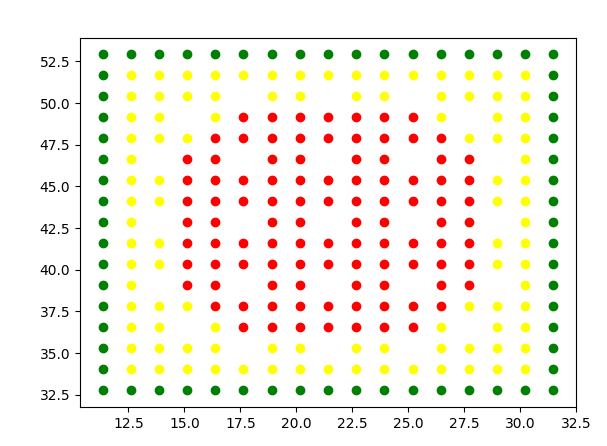
A representation of a C5G7 fuel assembly.
Here are the full files used in this example: